Airplane Ground Schools
Knowledge of Flying is Our passion.
Serving the General Aviation Community

|
|
EVOLUTION OF AIRBORNE NAVIGATION DATABASES
There are nearly as many different area navigation (RNAV) platforms operating in the National Airspace System (NAS) as there are aircraft types. The range of systems and their capabilities is greater now than at any other time in aviation history. From the simplest panel-mounted LOng RAnge Navigation (LORAN), to the moving- map display global positioning system (GPS) currently popular for general aviation aircraft, to the fully integrated flight management system (FMS) installed in corporate and commercial aircraft, the one common essential element is the database.

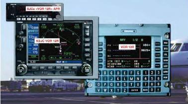
[Figure A-1. Area Navigation Receivers]
RNAV systems must not only be capable of determining an aircraft’s position over the surface of the earth, but they also must be able to determine the location of other fixes in order to navigate. These systems rely on airborne navigation databases to provide detailed information about these fixed points in the airspace or on the earth’s surface. Although, the location of these points is the primary concern for navigation, these databases can also provide many other useful pieces of information about a given location.
HISTORY AIRBORNE NAVIGATION DATABASES
In 1973, National Airlines installed the Collins ANS- 70 and AINS-70 RNAV systems in their DC-10 fleet; this marked the first commercial use of avionics that required navigation databases. A short time later, Delta Air Lines implemented the use of an ARMA Corporation RNAV system that also used a navigation database. Although the type of data stored in the two systems was basically identical, the designers created the databases to solve the individual problems of each system. In other words, the data was not interchangeable. This was not a problem because so few of the systems were in use, but as the implementation of RNAV systems expanded, a world standard for airborne navigation databases had to be created.
In 1973, Aeronautical Radio, Inc. (ARINC) sponsored the formation of a committee to standardize aeronautical databases. In 1975, this committee published the first standard (ARINC Specification 424), which has remained the worldwide-accepted format for coding airborne navigation databases.
There are many different types of RNAV systems certified for instrument flight rules (IFR) use in the NAS. The two most prevalent types are GPS and the multisensor FMS. Figure A-1. Area Navigation Receivers.
Most GPSs operate as stand-alone RNAV systems. A modern GPS unit accurately provides the pilot with the aircraft’s present position; however, it must use an airborne navigation database to determine its direction or distance from another location unless a latitude and longitude for that location is manually entered. The database provides the GPS with position information for navigation fixes so it may perform the required geodetic calculations to determine the appropriate tracks, headings, and distances to be flown.
Modern FMSs are capable of a large number of functions including basic en route navigation, complex departure and arrival navigation, fuel planning, and precise vertical navigation. Unlike stand-alone navigation systems, most FMSs use several navigation inputs. Typically, they formulate the aircraft’s current position using a combination of conventional distance measuring equipment (DME) signals, inertial navigation systems (INS), GPS receivers, or other RNAV devices. Like stand-alone navigation avionics, they rely heavily on airborne navigation databases to provide the information needed to perform their numerous functions.
DATABASE CAPABILITIES
The capabilities of airborne navigation databases depend largely on the way they are implemented by the avionics manufacturers. They can provide data about a large variety of locations, routes, and airspace segments for use by many different types of RNAV equipment. Databases can provide pilots with information regarding airports, air traffic control frequencies, runways, special use airspace, and much more. Without airborne navigation databases, RNAV would be extremely limited.
PRODUCTION AND DISTRIBUTION
In order to understand the capabilities and limitations of airborne navigation databases, pilots should have a basic understanding of the way databases are compiled and revised by the database provider and processed by the avionics manufacturer.
THE ROLE OF THE DATABASE PROVIDER
Compiling and maintaining a worldwide airborne navigation database is a large and complex job. Within the United States (U.S.), the Federal Aviation Administration (FAA) sources give the database providers information, in many different formats, which must be analyzed, edited, and processed before it can be coded into the database. In some cases, data from outside the U.S. must be translated into English so it may be analyzed and entered into the database. Once the data is coded following the specifications of ARINC 424 (see ARINC 424 later in this appendix), it must be continually updated and maintained.
Once the FAA notifies the database provider that a change is necessary, the update process begins.1 The change is incorporated into a 28-day airborne database revision cycle based on its assigned priority. If the information does not reach the coding phase prior to its cutoff date (the date that new aeronautical information can no longer be included in the next update), it is held out of revision until the next cycle. The cutoff date for aeronautical databases is typically 21 days prior to the effective date of the revision.2
The integrity of the data is ensured through a process called cyclic redundancy check (CRC). A CRC is an error detection algorithm capable of detecting small bit-level changes in a block of data. The CRC algorithm treats a data block as a single (large) binary value. The data block is divided by a fixed binary number (called a “generator polynomial”) whose form and magnitude is determined based on the level of integrity desired. The remainder of the division is the CRC value for the data block. This value is stored and transmitted with the corresponding data block. The integrity of the data is checked by reapplying the CRC algorithm prior to distribution, and later by the avionics equipment onboard the aircraft.
RELATIONSHIP BETWEEN EFB AND FMS DATABASES
The advent of the Electronic Flight Bag (EFB) discussed in Chapter 6 illustrates how the complexity of avionics databases is rapidly accelerating. The respective FMS and EFB databases remain independent of each other even though they may share some of the same data from the database provider’s master navigation database. For example, FMS and GPS databases both enable the retrieval of data for the onboard aircraft navigation system.
Additional data types that are not in the FMS database are extracted for the EFB database, allowing replacement of traditional printed instrument charts for the pilot.
1 The majority of the volume of official flight navigation data in the U.S. disseminated to database providers is primarily supplied by FAA sources. It is supplemented by airport managers, state civil aviation authorities, Department of Defense (DOD) organizations such as the National Geospatial-Intelligence Agency (NGA), branches of the military service, etc. Outside the U.S., the majority of official data is provided by each country’s civil aviation authority, the equivalent of the FAA, and disseminated as an aeronautical information publication (AIP).
2 The database provider extract occurs at the 21-day point. The edited extract is sent to the avionics manufacturer or prepared with the avionics-packing program. Data not coded by the 21-day point will not be contained in the database extract for the effective cycle. In order for the data to be in the database at this 21-day extract, the actual cutoff is more like 28 days before the effective date.
The three EFB charting applications include Terminal Charts, En route Moving Map (EMM), and Airport Moving Map (AMM). The Terminal Charts EFB charting application utilizes the same information and layout as the printed chart counterpart. The EMM application uses the same ARINC 424 en route data that is extracted for an FMS database, but adds additional information associated with aeronautical charting needs. The EFB AMM database is a new high-resolution geo-spatial database only for EFB use. The AMM shows aircraft proximity relative to the airport environment. Runways depicted in the AMM correlate to the runway depictions in the FMS navigation database. The other information in the AMM such as ramps, aprons, taxiways, buildings, and hold-short lines are not included in traditional ARINC 424 databases.
THE ROLE OF THE AVIONICS MANUFACTURER
When avionics manufacturers develop a piece of equipment that requires an airborne navigation database, they typically form an agreement with a database provider to supply the database for that new avionics platform. It is up to the manufacturer to determine what information to include in the database for their system. In some cases, the navigation data provider has to significantly reduce the number of records in the database to accommodate the storage capacity of the manufacturer’s new product.
The manufacturer must decide how its equipment will handle the records; decisions must be made about each field in the record. Each manufacturer can design their systems to manipulate the data fields in different ways, depending on the needs of the avionics user. Some fields may not be used at all. For instance, the ARINC primary record designed for individual runways may or may not be included in the database for a specific manufacturer’s machine. The avionics manufacturer might specify that the database include only runways greater than 4,000 feet. If the record is included in the tailored database, some of the fields in that record may not be used.
Another important fact to remember is that although there are standard naming conventions included in the ARINC 424 specification; each manufacturer determines how the names of fixes and procedures are displayed to the pilot. This means that although the database may specify the approach identifier field for the VOR/DME Runway 34 approach at Eugene Mahlon Sweet Airport (KEUG) in Eugene, Oregon, as “V34,” different avionics platforms may display the identifier in any way the manufacturer deems appropriate. For example, a GPS produced by one manufacturer might display the approach as “VOR 34,” whereas another might refer to the approach as “VOR/DME 34,” and an FMS produced by another manufacturer may refer to it as “VOR34.”
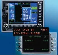
[Figure A-2 Naming Conventions of Three Different Systems for the VOR 34 Approach.]
These differences can cause visual inconsistencies between chart and GPS displays as well as confusion with approach clearances and other ATC instructions for pilots unfamiliar with specific manufacturer’s naming conventions.
The manufacturer determines the capabilities and limitations of an RNAV system based on the decisions that it makes regarding that system’s processing of the airborne navigation database.
USERS ROLE
Like paper charts, airborne navigation databases are subject to revision. Pilots using the databases are ultimately responsible for ensuring that the database they are operating with is current. This includes checking “NOTAM-type information” concerning errors that may be supplied by the avionics manufacturer or the database supplier. The database user is responsible for learning how the specific navigation equipment handles the navigation database. The manufacturer’s documentation is the pilot’s best source of information regarding the capabilities and limitations of a specific database.
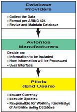
[Figure A-3. Database Roles]
.
COMPOSITION OF AIRBORNE NAVIGATION DATABASES
The concept of global position is an important concept of RNAV. Whereas short-range navigation deals primarily with azimuth and distance on a relatively small, flat surface, long-range point-to-point navigation must have a method of defining positions on the face of a large and imperfect sphere (or more specifically a mathematical reference surface called a geodetic datum). The latitude-longitude system is currently used to define these positions.
Each location/fix defined in an airborne navigation database is assigned latitude and longitude values in reference to a geodetic datum that can be used by avionics systems in navigation calculations.
THE WGS-84 REFERENCE DATUM
The idea of the earth as a sphere has existed in the scientific community since the early Greeks hypothesized about the shape and size of the earth over 2,000 years ago. This idea has become scientific fact, but it has been modified over time into the current theory of the earth’s shape. Since modern avionics rely on databases and mathematical geodetic computations to determine the distance and direction between points, those avionics systems must have some common frame of reference upon which to base those calculations. Unfortunately, the actual topographic shape of the earth’s surface is far too complex to be stored as a reference datum in the memory of today’s FMS or GPS data cards. Also, the mathematical calculations required to determine distance and direction using a reference datum of that complexity would be prohibitive. A simplified model of the earth’s surface solves both of these problems for today’s RNAV systems.
In 1735, the French Academy of Sciences sent an expedition to Peru and another to Lapland to measure the length of a meridian degree at each location. The expeditions determined conclusively that the earth is not a perfect sphere, but a flattened sphere, or what geologists call an ellipsoid of revolution. This means that the earth is flattened at the poles and bulges slightly at the equator. The most current measurements show that the polar diameter of the earth is about 7,900 statute miles and the equatorial diameter is 7,926 statute miles. This discovery proved to be very important in the field of geodetic survey because it increased the accuracy obtained when computing long distances using an earth model of this shape. This model of the earth is referred to as the Reference Ellipsoid, and combined with other mathematical parameters, it is used to define the reference for geodetic calculations or what is referred to as the geodetic datum.
Historically, each country has developed its own geodetic reference frame. In fact, until 1998 there were more than 160 different worldwide geodetic datums. This complicated accurate navigation between locations of great distance, especially if several reference datums are used along the route. In order to simplify RNAV and facilitate the use of GPS in the NAS, a common reference frame has evolved.
The reference datum currently being used in North America for airborne navigation databases is the North American Datum of 1983 (NAD-83), which for all practical navigation purposes is equivalent to the World Geodetic System of 1984 (WGS-84). Since WGS-84 is the geodetic datum that the constellation of GPS satellites are referenced to, it is the required datum for flight by reference to a GPS navigation receiver certified in accordance with FAA Technical Standard Order (TSO) C129A, Airborne Supplemental Navigation Equipment Using the Global Positioning System (GPS). The World Geodetic Datum was created by the Department of Defense in the 1960s as an earth-centered datum for military purposes, and one iteration of the model was adapted by the Department of Defense as a reference for GPS satellite orbits in 1987. The International Civil Aviation Organization (ICAO) and the international aviation community recognized the need for a common reference frame and set WGS-84 as the worldwide geodetic standard. All countries were obligated to convert to WGS-84 in January 1998. Many countries have complied with ICAO, but many still have not done so due to the complexity of the transformation and their limited survey resources.
ARINC 424
First published in 1975, the ARINC document, Navigation System Data Base (ARINC 424), sets forth the air transport industry’s recommended standards for the preparation of airborne navigation system reference data tapes. This document outlines the information to be included in the database for each specific navigation entity (i.e. airports, navigation aides [NAVAIDs], airways, and approaches), as well as the format in which the data is coded. The ARINC specification determines naming conventions.
RECORDS
The data included in an airborne navigation database is organized into ARINC 424 records. These records are strings of characters that make up complex descriptions of each navigation entity. There are 132 columns or spaces for characters in each record. Not all of the 132 character-positions are used for every record — some of the positions are left blank to permit like information to appear in the same columns of different records, and others are reserved for possible future record expansion. These records are divided into fields that contain specific pieces of information about the subject of the record. For instance, the primary record for an airport, such as KZXY, contains a field that describes the longest runway at that airport. The columns 28 through 30 in the record contain the first three digits in the longest runway’s length in feet. If the numbers 0, 6, and 5 were in the number 28, 29, and 30 columns respectively, the longest runway at KZXY would be recorded in the record as 6,500 feet (065).
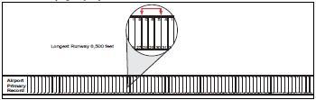
[Figure A-4 Longest Runway Field in an Airport Record.]
Columns 28 through 30, which are designated as “longest runway” in the airport record, would be a different field in the record for a very high frequency omni-directional range (VOR) or an airway. The record type determines what fields are included and how they are organized. For the purpose of discussion, ARINC records can be sorted into four general groups – fix records, simple route records, complex route records, and miscellaneous records. Although it is not important for pilots to have in-depth knowledge of all the fields contained in the ARINC 424 records, pilots should be aware of the types of records contained in the navigation database and their general content. Columns—The spaces for data entry on each record. One column can accommodate one character. Record—A single line of computer data made up of the fields necessary to define fully a single useful piece of data. Field—The collection of characters needed to define one item of information.
FIX RECORDS
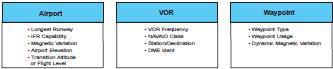
[Figure A-5. Unique Fields for Three Different Fix Records]
Database records that describe specific locations on the face of the earth can be considered fix records. NAVAIDs, waypoints, intersections, and airports are all examples of this type of record. These records can be used directly by avionics systems and can be included as parts of more complex records like airways or approaches. Within the 132 characters that make up a fix record, there are several fields that are generally common to all: record type, latitude, longitude, ICAO fix identifier, and ICAO location code. One exception is airports that use FAA identifiers. In addition, fix records contain many fields that are specific to the type of fix they describe. Figure A-5 on shows examples of field types for three different fix records.
In each of the above examples, magnetic variation is dealt with in a slightly different manner. Since the locations of these fixes are used to calculate the magnetic courses displayed in the cockpit, their records must include the location’s magnetic variation to be used in those calculations. In records for airports for instance, the magnetic variation is given as the difference in degrees between the measured values of true north and magnetic north at that location. The field labeled “Station Declination” in the record for a VOR differs only slightly in that it is the angular difference between true north and the zero degree radial of the NAVAID the last time the site was checked. The record for a waypoint, on the other hand, contains a field named “Dynamic Magnetic Variation,” which is simply a computer model calculated value instead of a measured value. Another concept pilots should understand relates to how aircraft make turns over navigation fixes. Fixes can be designated as fly-over or fly-by depending on how they are used in a specific route.
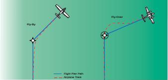
[Figure A-6 Unique Fields for Three Different Fix Records]
Under certain circumstances, a navigation fix is designated as fly-over. This simply means that the aircraft must actually pass directly over the fix before initiating a turn to a new course. Conversely, a fix may be designated fly-by, allowing an aircraft’s navigation system to use its turn anticipation feature, which ensures that the proper radius of turn is commanded to avoid overshooting the new course. Some RNAV systems are not programmed to fully use this feature. It is important to remember a fix can be coded as fly-over in one procedure, and fly-by in another, depending on how the fix is used.
SIMPLE ROUTE RECORDS
Route records are those that describe a flight path instead of a fixed position. Simple route records contain strings of fix records and information pertaining to how the fixes should be used by the navigation avionics. A Victor Airway, for example, is described in the database by a series of “en route airway records” that contain the names of fixes in the airway and information about how those fixes make up the airway. These records describe the way the fixes are used in the airway and contain important information including the fix identifier, sequence number, route type, required navigation performance (RNP), outbound and inbound magnetic courses (if appropriate), route distance, and minimum and maximum altitudes for the route.
Sequence number fields are a necessary addition to the navigation database because they allow the avionics system to track the fix order within the route. Most routes can be entered from any point and flown in both directions. The sequence number allows the avionics to keep track of the fixes in order, so that the proper flight path can be followed starting anywhere within the route.
COMPLEX ROUTE RECORDS
Complex route records include those strings of fixes that describe complex flight paths like standard instrument departures (SIDs), standard terminal arrival routes (STARs), and instrument approach procedures. Like simple routes, these records contain the names of fixes to be used in the route as well as instructions on how the route will be flown. However, there are several fields included in these records that are unique to this type.
SID procedures are examples of complex routes that are coded in airborne navigation databases. The record for a SID includes many of the same types of information that are found in the en route airway record, and many other pieces of information that pertain only to complex flight paths. Some examples of the fields included in the SID record are the airport identifier, SID identifier, transition identifier, turn direction, recommended NAVAID, magnetic course, and path/terminator.
MISCELLANEOUS RECORDS
There are several other types of records coded into airborne navigation databases, most of which deal with airspace or communications. For example, there are records for restricted airspace, airport minimum safe altitudes, and grid minimum off route altitudes (MORAs). These records have many individual and unique fields that combine to describe the record’s subject. Some are used by avionics manufacturers, some are not, depending on the individual capabilities of each RNAV unit.
THE PATH/TERMINATOR CONCEPT
One of the most important concepts for pilots to learn regarding the limitations of RNAV equipment has to do with the way these systems deal with the “Path/Terminator” field included in complex route records.
The first RNAV systems were capable of only one type of navigation: they could fly directly to a fix. This was not a problem when operating in the en route environment in which airways are mostly made up of direct (or very nearly direct) routes between fixes. The instrument approaches that were designed for RNAV also presented no problem for these systems and the databases they used since they consisted mainly of GPS overlay approaches that demanded only direct point-topoint navigation. The desire for RNAV equipment to have the ability to follow more complicated flight paths necessitated the development of the “Path/Terminator” field that is included in complex route records.
There are currently 23 different Path/Terminators in the ARINC 424 standard. They enable RNAV systems to follow the complex paths that make up instrument departures, arrivals, and approaches. They describe to navigation avionics a path to be followed and the criteria that must be met before the path concludes and the next path begins. One of the simplest and most common Path/Terminators is the track to a fix (TF), which is used to define the great circle route between two known points.
Additional information on Path/Terminator leg types is contained previous sections.

[Figure A-7 Path/Terminator. A Path/Terminator value of a TF
leg indicates a great circle track directly from one fix to the next]
The GRAND JUNCTION FOUR DEPARTURE for Walker Field in Grand Junction, Colorado, provides a good example of another type of Path/Terminator.
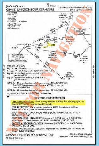
[Figure A-8 Grand Junction Four Departure]
When this procedure is coded into the navigation database, the person entering the data into the records must identify the individual legs of the flight path and then determine which type of terminator should be used.
The first leg of the departure for Runway 11 is a climb via runway heading to 6,000 feet mean sea level (MSL) and then a climbing right turn direct to a fix. When this is entered into the database, a heading to an altitude (VA) value must be entered into the record’s Path/Terminator field for the first leg of the departure route. This Path/Terminator tells the avionics to provide course guidance based on heading, until the aircraft reaches 6,000 feet, and then the system begins providing course guidance for the next leg. After reaching 6,000 feet, the procedure calls for a right turn direct to the Grand Junction (JNC) VORTAC. This leg is coded into the database using the Path/Terminator direct to a fix (DF) value, which defines an unspecified track starting from an undefined position to a specific database fix. After reaching the JNC VORTAC the only Path/Terminator value used in the procedure is a TF leg.
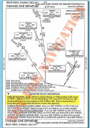
[Figure A-9. Channel One Departure.]
Another commonly used Path/Terminator value is heading to a radial (VR). Figure A-9 shows the CHANNEL ONE DEPARTURE procedure for Santa Ana, California. The first leg of the runway 19L/R procedure requires a climb on runway heading until crossing the I-SNA 1 DME fix or the SLI R-118, this leg must be coded into the database using the VR value in the Path/Terminator field. After crossing the I-SNA 1 DME fix or the SLI R-118, the avionics should cycle to the next leg of the procedure that in this case, is a climb on a heading of 175° until crossing SLI R-132. This leg is also coded with a VR Path/Terminator. The next leg of the procedure consists of a heading of 200° until intercepting the SXC R-084. In order for the avionics to correctly process this leg, the database record must include the heading to an intercept (VI) value in the Path/Terminator field. This value directs the avionics to follow a specified heading to intercept the subsequent leg at an unspecified position.
The Path/Terminator concept is a very important part of airborne navigation database coding. In general, it is not necessary for pilots to have an in-depth knowledge of the ARINC coding standards; however, pilots should be familiar with the concepts related to coding in order to understand the limitations of specific RNAV systems that use databases. For a more detailed discussion of coding standards, refer to ARINC Specification 424-15 Navigation System Data Base.
OPERATIONAL LIMITATIONS OF AIRBORNE NAVIGATION DATABASES
Understanding the capabilities and limitations of the navigation systems installed in an aircraft is one of the pilot’s biggest concerns for IFR flight. Considering the vast number of RNAV systems and pilot interfaces available today, it is critical that pilots and flight crews be familiar with the manufacturer’s operating manual for each RNAV system they operate and achieve and retain proficiency operating those systems in the IFR environment.
RELIANCE ON NAVIGATION AUTOMATION
Most professional and general aviation pilots are familiar with the possible human factors issues related to cockpit automation. It is particularly important to consider those issues when using airborne navigation databases. Although modern avionics can provide precise guidance throughout all phases of flight including complex departures and arrivals, not all systems have the same capabilities. RNAV equipment installed in some aircraft is limited to direct route point-to-point navigation. Therefore, it is very important for pilots to familiarize themselves with the capabilities of their systems through review of the manufacturer documentation.
Most modern RNAV systems are contained within an integrated avionics system that receives input from several different navigation and aircraft system sensors. These integrated systems provide so much information that pilots may sometimes fail to recognize errors in navigation caused by database discrepancies or misuse. Pilots must constantly ensure that the data they enter into their avionics is accurate and current. Once the transition to RNAV is made during a flight, pilots and flight crews must always be capable and ready to revert to conventional means of navigation if problems arise.
STORAGE LIMITATIONS
As the data in a worldwide database grows more detailed, the required data storage space increases. Over the years that panel-mounted GPS and FMS have developed, the size of the commercially available airborne navigation databases has grown exponentially. Some manufacturer’s systems have kept up with this growth and some have not. Many of the limitations of older RNAV systems are a direct result of limited data storage capacity. For this reason, avionics manufacturers must make decisions regarding which types of data records will be extracted from the master database to be included with their system. For instance, older GPS units rarely include all of the waypoints that are coded into master databases. Even some modern FMSs, which typically have much larger storage capacity, do not include all of the data that is available from the database producers. The manufacturers often choose not to include certain types of data that they think is of low importance to the usability of the unit. For example, manufacturers of FMSs used in large airplanes may elect not to include airports where the longest runway is less than 3,000 feet or to include all the procedures for an airport.
Manufacturers of RNAV equipment can reduce the size of the data storage required in their avionics by limiting the geographic area the database covers. Like paper charts, the amount of data that needs to be carried with the aircraft is directly related to the size of the coverage area. Depending on the data storage that is available, this means that the larger the required coverage area, the less detailed the database can be.
Again, due to the wide range of possible storage capacities, and the number of different manufacturers and product lines, the manufacturer’s documentation is the pilot’s best source of information regarding limitations caused by storage capacity of RNAV avionics.
PATH/TERMINATOR LIMITATIONS
How a specific RNAV system deals with Path/Terminators is of great importance to pilots operating with airborne navigation databases. Some early RNAV systems may ignore this field completely. The ILS/DME RWY 2 approach at Durango, Colorado, provides an example of problems that may arise from the lack of Path/Terminator capability in RNAV systems. Although approaches of this type are authorized only for sufficiently equipped RNAV systems, it is possible that a pilot may elect to fly the approach with conventional navigation, and then reengage RNAV during a missed approach. If this missed approach is flown using an RNAV system that does not use Path/Terminator values, then the system will most likely ignore the first two legs of the procedure. This will cause the RNAV equipment to direct the pilot to make an immediate turn toward the Durango VOR instead of flying the series of headings that terminate at specific altitudes as dictated by the approach procedure.

[Figure A-10 ILS/DME Runway 2 in Durango, Colorado.]
Pilots must be aware of their individual systems Path/Terminator handling characteristics and always review the manufacturer’s documentation to familiarize themselves with the capabilities of the RNAV equipment they are operating. Pilots should be aware that some RNAV equipment was designed without the fly-over capability that was discussed earlier in this appendix. This can cause problems for pilots attempting to use this equipment to fly complex flight paths in the departure, arrival, or approach environments.
CHARTING/DATABASE INCONSISTENCIES
It is important for pilots to remember that many inconsistencies may exist between aeronautical charts and airborne navigation databases. Since there are so many A-11 sources of information included in the production of these materials, and the data is manipulated by several different organizations before it eventually is displayed on RNAV equipment, the possibility is high that there will be noticeable differences between the charts and the databases. However, only the inconsistencies that may be built into the databases are addressed in this discussion.
NAMING CONVENTIONS
As was discussed earlier in this appendix, obvious differences exist between the names of procedures shown on charts and those that appear on the displays of many Figure A-10. ILS/DME Runway 2 in Durango, Colorado. A-12 RNAV systems. Most of these differences can be accounted for simply by the way the avionics manufacturers elect to display the information to the pilot. It is the avionics manufacturer that creates the interface between the pilot and the database, so the ARINC 424 naming conventions do not really apply. For example, the VOR 12R approach in San Jose, California, might be displayed several different ways depending on how the manufacturer designs the pilot interface.
[Figure A-11 Three Different Formats for the Same Approach]
Some systems display procedure names exactly as they are charted, but many do not.
Although the three different names shown in Figure A-11 identify the same approach, the navigation system manufacturer has manipulated them into different formats to work within the framework of each specific machine. Of course, the data provided to the manufacturer in ARINC 424 format designates the approach as a 132-character data record that is not appropriate for display, so the manufacturer must create its own naming conventions for each of its systems.
NAVAIDs are subject to naming discrepancies. This problem is complicated by the fact that multiple NAVAIDs can be designated with the same identifier. VOR XYZ may occur several times in a provider’s database, so the avionics manufacturer must design a way to identify these fixes by a more specific means than the three-letter identifier. Selection of geographic region is used in most instances to narrow the pilot’s selection of NAVAIDs with like identifiers.
Non-directional beacons (NDBs) and locator outer markers (LOMs) can be displayed differently than they are charted. When the first airborne navigation databases were being implemented, NDBs were included in the database as waypoints instead of NAVAIDs. This necessitated the use of five character identifiers for NDBs. Eventually, the NDBs were coded into the database as NAVAIDs, but many of the RNAV systems in use today continue to use the five-character identifier. These systems display the characters “NB” after the charted NDB identifier. Therefore, NDB ABC would be displayed as “ABCNB.”
Other systems refer to NDB NAVAIDs using either the NDB’s charted name if it is five or fewer letters, or the one to three character identifier. PENDY NDB located in North Carolina, for instance, is displayed on some systems as “PENDY,” while other systems might only display the NDBs identifier “ACZ.”
[Figure A-12 Manufacturers Naming Conventions]
ISSUES RELATED TO MAGNETIC VARIATION
Magnetic variations for locations coded into airborne navigation databases can be acquired in several ways. In many cases they are supplied by government agencies in the “Epoch Year Variation” format. Theoretically, this value is determined by government sources and published for public use every five years. Providers of airborne navigation databases do not use annual drift values; instead the database uses the “Epoch Year Variation” until it is updated by the appropriate source provider. In the U.S., this is the National Oceanic and Atmospheric Administration (NOAA). In some cases the variation for a given location is a value that has been calculated by the avionics system. These “Dynamic Magnetic Variation” values can be different than those used for locations during aeronautical charting. Figure A-11. Three Different Formats for the Same Approach. It is important to remember that even though ARINC standard records for airways and other procedures contain the appropriate magnetic headings and radials for routes, most RNAV systems do not use this information for en route flight. Magnetic courses are computed by airborne avionics using geodesic calculations based on the latitude and longitude of the waypoints along the route. Since all of these calculations are based on true north, the navigation system must have a way to account for magnetic variation. This can cause many discrepancies between the charted values and the values derived by the avionics. Some navigation receivers use the magnetic variation, or station declination, contained in the ARINC data records to make calculations, while other systems have independent ways of determining the magnetic variation in the general area of the VOR or waypoint. Discrepancies can occur for many reasons. Even when the variation values from the database are used, the resulting calculated course might be different from the course depicted on the charts. Using the magnetic variation for the region, instead of the actual station declination, can result in differences between charted and calculated courses. Station declination is only updated when a NAVAID is “site checked” by the governing authority that controls it, so it is often different than the current magnetic variation for that location. Using an onboard means of determining variation usually entails coding some sort of earth model into the avionics memory. Since magnetic variation for a given location changes predictably over time, this model may only be correct for one time in the lifecycle of the avionics. This means that if the intended lifecycle of a GPS unit were 20 years, the point at which the variation model might be correct would be when the GPS unit was 10 years old. The discrepancy would be greatest when the unit was new, and again near the end of its life span. Another issue that can cause slight differences between charted course values and those in the database occurs when a terminal procedure is coded using “Magnetic Variation of Record.”When approaches or other procedures are designed, the designers use specific rules to apply variation to a given procedure. Some controlling government agencies may elect to use the Epoch Year Variation of an airport to define entire procedures at that airport. This may cause the course discrepancies between the charted value and the value calculated using the actual variations from the database.
ISSUES RELATED TO REVISION CYCLE
Pilots should be aware that the length of the airborne navigation database revision cycle could cause discrepancies between aeronautical charts and information derived from the database. One important difference between aeronautical charts and databases is the length of cutoff time. Cutoff refers to the length of time between the last day that changes can be made in the revision, and the date the information becomes effective. Aeronautical charts typically have a cutoff date of 10 days prior to the effective date of the charts. Figure A-12. Manufacturers Naming Conventions. A-13 A-14
EVOLUTION OF RNAV
The use of RNAV equipment utilizing airborne navigation databases has significantly increased the capabilities of aircraft operating in the NAS. Pilots are now capable of direct flight over long distances with increasing precision. Furthermore, RNAV (RNP) instrument approach procedures are now capable of precision curved flight tracks.
 RF Leg Segment and Associated FMS Control Display Unit.JPG)
[Figure A-13. Example of an RNAV (RNP) RF Leg Segment and Associated FMS Control Display Unit]
The availability of RNAV equipment has reached all facets of commercial, corporate, and general aviation. Airborne navigation databases have played a large role in this progress.
Although database providers have implemented a standard for airborne navigation databases, pilots must understand that RNAV is an evolving technology. Information published on current aeronautical charts must be used in cases where discrepancies or uncertainties exist with a navigation database. There are many variables relating to database, manufacturer, and user limitations that must be considered when operating with any RNAV equipment. Manufacturer documentation, aeronautical charts, and FAA publications are the pilot’s best source of information regarding these capabilities and limitations.
(Courtesy FAA)
Copyright © 2008 AirplaneGroundSchools.com | All Rights Reserved
Design G. Wolfgang | W3C XHTML 1.0 | W3C CSS 2.0
Courtesy Open Web Design![]() Thanks to Florida Vacation Homes
Thanks to Florida Vacation Homes