Airplane Ground Schools
Knowledge of Flying is Our passion.
Serving the General Aviation Community
|
|
Aerodynamics in Flight
FORCES ACTING ON THE AIRPLANE
In some respects at least, how well a pilot performs in flight depends upon the ability to plan and coordinate the use of the power and flight controls for changing the forces of thrust, drag, lift, and weight. It is the balance between these forces that the pilot must always control. The better the understanding of the forces and means of controlling them, the greater will be the pilot’s skill at doing so.
The following defines these forces in relation to straight-and-level, unaccelerated flight.
Thrust is the forward force produced by the powerplant/ propeller. It opposes or overcomes the force of drag. As a general rule, it is said to act parallel to the longitudinal axis. However, this is not always the case as will be explained later.
Drag is a rearward, retarding force, and is caused by disruption of airflow by the wing, fuselage, and other protruding objects. Drag opposes thrust, and acts rearward parallel to the relative wind.
Weight is the combined load of the airplane itself, the crew, the fuel, and the cargo or baggage. Weight pulls the airplane downward because of the force of gravity. It opposes lift, and acts vertically downward through the airplane’s center of gravity.
Lift opposes the downward force of weight, is produced by the dynamic effect of the air acting on the wing, and acts perpendicular to the flightpath through the wing’s center of lift.
In steady flight, the sum of these opposing forces is equal to zero. There can be no unbalanced forces in steady, straight flight (Newton’s Third Law). This is true whether flying level or when climbing or descending. This is not the same thing as saying that the four forces are all equal. It simply means that the opposing forces are equal to, and thereby cancel the effects of, each other. Often the relationship between the four forces has been erroneously explained or illustrated in such a way that this point is obscured. Consider figure 3-1, for the four forces acting on an airplane during flight.
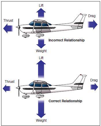
[Figure 3-1. The four forces acting on an airplane during flight]
In the upper illustration the force vectors of thrust, drag, lift, and weight appear to be equal in value. The usual explanation states (without stipulating that thrust and drag do not equal weight and lift) that thrust equals drag and lift equals weight as shown in the lower illustration. This basically true statement must be understood or it can be misleading. It should be understood that in straight, level, unaccelerated flight, it is true that the opposing lift/weight forces are equal, but they are also greater than the opposing forces of thrust/drag that are equal only to each other; not to lift/weight. To be correct about it, it must be said that in steady flight:
• The sum of all upward forces (not just lift) equals the sum of all downward forces (not just weight).
• The sum of all forward forces (not just thrust) equals the sum of all backward forces (not just drag).
This refinement of the old “thrust equals drag; lift equals weight” formula takes into account the fact that in climbs a portion of thrust, since it is directed upward, acts as if it were lift; and a portion of weight, since it is directed backward, acts as if it were drag. In glides, a portion of the weight vector is directed forward, and therefore acts as thrust. In other words, any time the flightpath of the airplane is not horizontal, lift, weight, thrust, and drag vectors must each be broken down into two components.
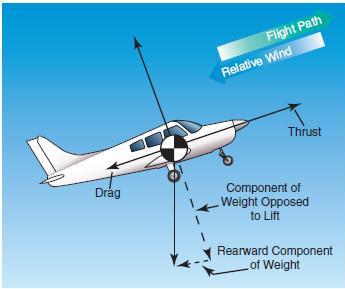
[Figure 3-2. Force vectors during a stabilized climb]
Discussions of the preceding concepts are frequently omitted in aeronautical texts/handbooks/manuals. The reason is not that they are of no consequence, but because by omitting such discussions, the main ideas with respect to the aerodynamic forces acting upon an airplane in flight can be presented in their most essential elements without being involved in the technicalities of the aerodynamicist. In point of fact, considering only level flight, and normal climbs and glides in a steady state, it is still true that wing lift is the really important upward force, and weight is the really important downward force.
Frequently, much of the difficulty encountered in explaining the forces that act upon an airplane is largely a matter of language and its meaning. For example, pilots have long believed that an airplane climbs because of excess lift. This is not true if one is thinking in terms of wing lift alone. It is true, however, if by lift it is meant the sum total of all “upward forces.” But when referring to the “lift of thrust” or the “thrust of weight,” the definitions previously established for these forces are no longer valid and complicate matters. It is this impreciseness in language that affords the excuse to engage in arguments, largely academic, over refinements to basic principles.
Though the forces acting on an airplane have already been defined, a discussion in more detail to establish how the pilot uses them to produce controlled flight is appropriate.
THRUST
Before the airplane begins to move, thrust must be exerted. It continues to move and gain speed until thrust and drag are equal. In order to maintain a constant airspeed, thrust and drag must remain equal, just as lift and weight must be equal to maintain a constant altitude. If in level flight, the engine power is reduced, the thrust is lessened, and the airplane slows down. As long as the thrust is less than the drag, the airplane continues to decelerate until its airspeed is insufficient to support it in the air.
Likewise, if the engine power is increased, thrust becomes greater than drag and the airspeed increases. As long as the thrust continues to be greater than the drag, the airplane continues to accelerate. When drag equals thrust, the airplane flies at a constant airspeed.
Straight-and-level flight may be sustained at speeds from very slow to very fast. The pilot must coordinate angle of attack and thrust in all speed regimes if the airplane is to be held in level flight. Roughly, these regimes can be grouped in three categories: low-speed flight, cruising flight, and high-speed flight. When the airspeed is low, the angle of attack must be relatively high to increase lift if the balance between lift and weight is to be maintained.
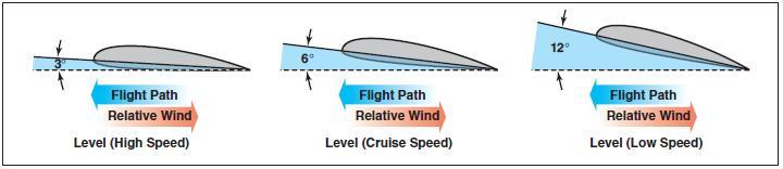
[Figure 3-3 angle of attack in flight]
If thrust decreases and airspeed decreases, lift becomes less than weight and the airplane will start to descend. To maintain level flight, the pilot can increase the angle of attack an amount which will generate a lift force again equal to the weight of the airplane and while the airplane will be flying more slowly, it will still maintain level flight if the pilot has properly coordinated thrust and angle of attack.
Straight-and-level flight in the slow speed regime provides some interesting conditions relative to the equilibrium of forces, because with the airplane in a nose-high attitude, there is a vertical component of thrust that helps support the airplane. For one thing, wing loading tends to be less than would be expected. Most pilots are aware that an airplane will stall, other conditions being equal, at a slower speed with the power on than with the power off. (Induced airflow over the wings from the propeller also contributes to this.) However, if analysis is restricted to the four forces as they are usually defined, one can say that in straight-and-level slow speed flight the thrust is equal to drag, and lift is equal to weight.
During straight-and level-flight when thrust is increased and the airspeed increases, the angle of attack must be decreased. That is, if changes have been coordinated, the airplane will still remain in level flight but at a higher speed when the proper relationship between thrust and angle of attack is established.
If the angle of attack were not coordinated (decreased) with this increase of thrust, the airplane would climb. But decreasing the angle of attack modifies the lift, keeping it equal to the weight, and if properly done, the airplane still remains in level flight. Level flight at even slightly negative angles of attack is possible at very high speed. It is evident then, that level flight can be performed with any angle of attack between stalling angle and the relatively small negative angles found at high speed.
DRAG
Drag in flight is of two basic types: parasite drag and induced drag. The first is called parasite because it in no way functions to aid flight, while the second is induced or created as a result of the wing developing lift.
Parasite drag is composed of two basic elements: form drag, resulting from the disruption of the streamline flow; and the resistance of skin friction.
Of the two components of parasite drag, form drag is the easier to reduce when designing an airplane. In general, a more streamlined object produces the best form to reduce parasite drag.
Skin friction is the type of parasite drag that is most difficult to reduce. No surface is perfectly smooth. Even machined surfaces, when inspected through magnification, have a ragged, uneven appearance. This rough surface will deflect the streamlines of air on the surface, causing resistance to smooth airflow. Skin friction can be minimized by employing a glossy, flat finish to surfaces, and by eliminating protruding rivet heads, roughness, and other irregularities.
Another element must be added to the consideration of parasite drag when designing an airplane. This drag combines the effects of form drag and skin friction and is called interference drag. If two objects are placed adjacent to one another, the resulting turbulence produced may be 50 to 200 percent greater than the parts tested separately.
The three elements, form drag, skin friction, and interference drag, are all computed to determine parasite drag on an airplane.
Shape of an object is a big factor in parasite drag. However, indicated airspeed is an equally important factor when speaking of parasite drag. The profile drag of a streamlined object held in a fixed position relative to the airflow increases approximately as the square of the velocity; thus, doubling the airspeed increases the drag four times, and tripling the airspeed increases the drag nine times. This relationship, however, holds good only at comparatively low subsonic speeds. At some higher airspeeds, the rate at which profile drag has been increased with speed suddenly begins to increase more rapidly.
The second basic type of drag is induced drag. It is an established physical fact that no system, which does work in the mechanical sense, can be 100 percent efficient. This means that whatever the nature of the system, the required work is obtained at the expense of certain additional work that is dissipated or lost in the system. The more efficient the system, the smaller this loss.
In level flight the aerodynamic properties of the wing produce a required lift, but this can be obtained only at the expense of a certain penalty. The name given to this penalty is induced drag. Induced drag is inherent whenever a wing is producing lift and, in fact, this type of drag is inseparable from the production of lift. Consequently, it is always present if lift is produced.
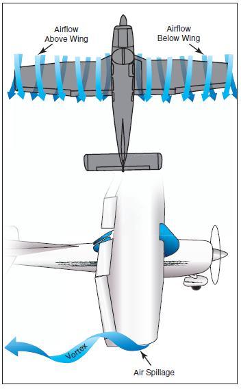
The wing produces the lift force by making use of the energy of the free airstream. Whenever the wing is producing lift, the pressure on the lower surface of the wing is greater than that on the upper surface. As a result, the air tends to flow from the high pressure area below the wingtip upward to the low pressure area above the wing. In the vicinity of the wingtips, there is a tendency for these pressures to equalize, resulting in a lateral flow outward from the underside to the upper surface of the wing. This lateral flow imparts a rotational velocity to the air at the wingtips and trails behind the wing. Therefore, flow about the wingtips will be in the form of two vortices trailing behind as the wings move on.
When the airplane is viewed from the tail, these vortices will circulate counterclockwise about the right wingtip and clockwise about the left wingtip.
[Figure 3-4 wingtip vortices]
Bearing in mind the direction of rotation of these vortices, it can be seen that they induce an upward flow of air beyond the wingtip, and a downwash flow behind the wing’s trailing edge. This induced downwash has nothing in common with the downwash that is necessary to produce lift. It is, in fact, the source of induced drag. The greater the size and strength of the vortices and consequent downwash component on the net airflow over the wing, the greater the induced drag effect becomes. This downwash over the top of the wing at the tip has the same effect as bending the lift vector rearward; therefore, the lift is slightly aft of perpendicular to the relative wind, creating a rearward lift component. This is induced drag.
It should be remembered that in order to create a greater negative pressure on the top of the wing, the wing can be inclined to a higher angle of attack; also, that if the angle of attack of an asymmetrical wing were zero, there would be no pressure differential and consequently no downwash component; therefore, no induced drag. In any case, as angle of attack increases, induced drag increases proportionally.
To state this another way—the lower the airspeed the greater the angle of attack required to produce lift equal to the airplane’s weight and consequently, the greater will be the induced drag. The amount of induced drag varies inversely as the square of the airspeed.
[Figure 3-5 drag coefficient versus speed]
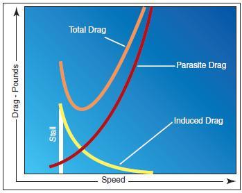
From the foregoing discussion, it can be noted that parasite drag increases as the square of the airspeed, and induced drag varies inversely as the square of the airspeed. It can be seen that as airspeed decreases to near the stalling speed, the total drag becomes greater, due mainly to the sharp rise in induced drag. Similarly, as the airspeed reaches the terminal velocity of the airplane, the total drag again increases rapidly, due to the sharp increase of parasite drag. As seen in figure 3-5, at some given airspeed, total drag is at its maximum amount. This is very important in figuring the maximum endurance and range of airplanes; for when drag is at a minimum, power required to overcome drag is also at a minimum.
[Figure 3-6 Lift coefficients at various angles of attack]
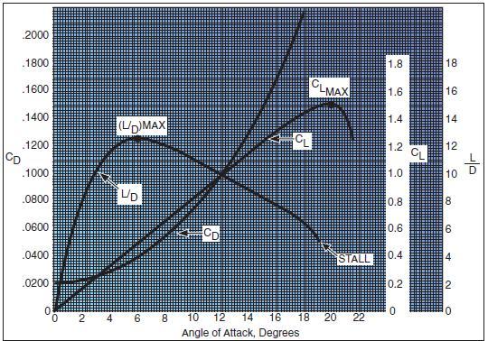
To understand the effect of lift and drag on an airplane in flight, both must be combined and the lift/drag ratio considered. With the lift and drag data available for various airspeeds of the airplane in steady, unaccelerated flight, the proportions of CL (Coefficient of Lift) and CD (Coefficient of Drag) can be calculated for each specific angle of attack. The resulting plot for lift/drag ratio with angle of attack shows that L/D increases to some maximum, then decreases at the higher lift coefficients and angles of attack, as shown in figure 3-6. Note that the maximum lift/drag ratio, (L/D max) occurs at one specific angle of attack and lift coefficient. If the airplane is operated in steady flight at L/D max, the total drag is at a minimum. Any angle of attack lower or higher than that for L/D max reduces the lift/drag ratio and consequently increases the total drag for a given airplane’s lift.
The location of the center of gravity (CG) is determined by the general design of each particular airplane. The designers determine how far the center of pressure (CP) will travel. They then fix the center of gravity forward of the center of pressure for the corresponding flight speed in order to provide an adequate restoring moment to retain flight equilibrium.
The configuration of an airplane has a great effect on the lift/drag ratio. The high performance sailplane may have extremely high lift/drag ratios. The supersonic fighter may have seemingly low lift/drag ratios in subsonic flight, but the airplane configurations required for supersonic flight (and high L/Ds at high Mach numbers) cause this situation.
WEIGHT
Gravity is the pulling force that tends to draw all bodies to the center of the earth. The center of gravity (CG) may be considered as a point at which all the weight of the airplane is concentrated. If the airplane were supported at its exact center of gravity, it would balance in any attitude. It will be noted that center of gravity is of major importance in an airplane, for its position has a great bearing upon stability.
The location of the center of gravity is determined by the general design of each particular airplane. The designers determine how far the center of pressure (CP) will travel. They then fix the center of gravity forward of the center of pressure for the corresponding flight speed in order to provide an adequate restoring moment to retain flight equilibrium.
Weight has a definite relationship with lift, and thrust with drag. This relationship is simple, but important in understanding the aerodynamics of flying. Lift is the upward force on the wing acting perpendicular to the relative wind. Lift is required to counteract the airplane’s weight (which is caused by the force of gravity acting on the mass of the airplane). This weight (gravity) force acts downward through the airplane’s center of gravity. In stabilized level flight, when the lift force is equal to the weight force, the airplane is in a state of equilibrium and neither gains nor loses altitude. If lift becomes less than weight, the airplane loses altitude. When the lift is greater than weight, the airplane gains altitude.
LIFT
The pilot can control the lift. Any time the control wheel is more fore or aft, the angle of attack is changed. As angle of attack increases, lift increases (all other factors being equal). When the airplane reaches the maximum angle of attack, lift begins to diminish rapidly. This is the stalling angle of attack, or burble point.
Before proceeding further with lift and how it can be controlled, velocity must be interjected. The shape of the wing cannot be effective unless it continually keeps “attacking” new air. If an airplane is to keep flying, it must keep moving. Lift is proportional to the square of the airplane’s velocity. For example, an airplane traveling at 200 knots has four times the lift as the same airplane traveling at 100 knots, if the angle of attack and other factors remain constant.
Actually, the airplane could not continue to travel in level flight at a constant altitude and maintain the same angle of attack if the velocity is increased. The lift would increase and the airplane would climb as a result of the increased lift force. Therefore, to maintain the lift and weight forces in balance, and to keep the airplane “straight and level” (not accelerating upward) in a state of equilibrium, as velocity is increased, lift must be decreased. This is normally accomplished by reducing the angle of attack; i.e., lowering the nose. Conversely, as the airplane is slowed, the decreasing velocity requires increasing the angle of attack to maintain lift sufficient to maintain flight. There is, of course, a limit to how far the angle of attack can be increased, if a stall is to be avoided.
Therefore, it may be concluded that for every angle of attack there is a corresponding indicated airspeed required to maintain altitude in steady, unaccelerated flight—all other factors being constant. (Bear in mind this is only true if maintaining “level flight.”) Since an airfoil will always stall at the same angle of attack, if increasing weight, lift must also be increased, and the only method for doing so is by increased velocity if the angle of attack is held constant just short of the “critical” or stalling angle of attack.
Lift and drag also vary directly with the density of the air. Density is affected by several factors: pressure, temperature, and humidity. Remember, at an altitude of 18,000 feet, the density of the air has one-half the density of air at sea level. Therefore, in order to maintain its lift at a higher altitude, an airplane must fly at a greater true airspeed for any given angle of attack.
Furthermore, warm air is less dense than cool air, and moist air is less dense than dry air. Thus, on a hot humid day, an airplane must be flown at a greater true airspeed for any given angle of attack than on a cool, dry day.
If the density factor is decreased and the total lift must equal the total weight to remain in flight, it follows that one of the other factors must be increased. The factors usually increased are the airspeed or the angle of attack, because these factors can be controlled directly by the pilot.
It should also be pointed out that lift varies directly with the wing area, provided there is no change in the wing’s planform. If the wings have the same proportion and airfoil sections, a wing with a planform area of 200 square feet lifts twice as much at the same angle of attack as a wing with an area of 100 square feet.
As can be seen, two major factors from the pilot’s viewpoint are lift and velocity because these are the two that can be controlled most readily and accurately. Of course, the pilot can also control density by adjusting the altitude and can control wing area if the airplane happens to have flaps of the type that enlarge wing area. However, for most situations, the pilot is controlling lift and velocity to maneuver the airplane. For instance, in straight-and-level flight, cruising along at a constant altitude, altitude is maintained by adjusting lift to match the airplane’s velocity or cruise airspeed, while maintaining a state of equilibrium where lift equals weight. In an approach to landing, when the pilot wishes to land as slowly as practical, it is necessary to increase lift to near maximum to maintain lift equal to the weight of the airplane.
WINGTIP VORTICES
The action of the airfoil that gives an airplane lift also causes induced drag. It was determined that when a wing is flown at a positive angle of attack, a pressure differential exists between the upper and lower surfaces of the wing—that is, the pressure above the wing is less than atmospheric pressure and the pressure below the wing is equal to or greater than atmospheric pressure. Since air always moves from high pressure toward low pressure, and the path of least resistance is toward the airplane’s wingtips, there is a spanwise movement of air from the bottom of the wing outward from the fuselage around the wingtips. This flow of air results in “spillage” over the wingtips, thereby setting up a whirlpool of air called a “vortex.” At the same time, the air on the upper surface of the wing has a tendency to flow in toward the fuselage and off the trailing edge. This air current forms a similar vortex at the inboard portion of the trailing edge of the wing, but because the fuselage limits the inward flow, the vortex is insignificant. Consequently, the deviation in flow direction is greatest at the wingtips where the unrestricted lateral flow is the strongest. As the air curls upward around the wingtip, it combines with the wing’s downwash to form a fast spinning trailing vortex. These vortices increase drag because of energy spent in producing the turbulence. It can be seen, then, that whenever the wing is producing lift, induced drag occurs, and wingtip vortices are created.
Just as lift increases with an increase in angle of attack, induced drag also increases. This occurs because as the angle of attack is increased, there is a greater pressure difference between the top and bottom of the wing, and a greater lateral flow of air; consequently, this causes more violent vortices to be set up, resulting in more turbulence and more induced drag.
The intensity or strength of the wingtip vortices is directly proportional to the weight of the airplane and inversely proportional to the wingspan and speed of the airplane. The heavier and slower the airplane, the greater the angle of attack and the stronger the wingtip vortices. Thus, an airplane will create wingtip vortices with maximum strength occurring during the takeoff, climb, and landing phases of flight.
GROUND EFFECT
It is possible to fly an airplane just clear of the ground (or water) at a slightly slower airspeed than that required to sustain level flight at higher altitudes. This is the result of a phenomenon, which is better known than understood even by some experienced pilots.
When an airplane in flight gets within several feet from the ground surface, a change occurs in the threedimensional flow pattern around the airplane because the vertical component of the airflow around the wing is restricted by the ground surface. This alters the wing’s upwash, downwash, and wingtip vortices.
[Figure 3-7 wing in ground effect aerodynamics]
These general effects due to the presence of the ground are referred to as “ground effect.” Ground effect, then, is due to the interference of the ground (or water) surface with the airflow patterns about the airplane in flight. While the aerodynamic characteristics of the tail surfaces and the fuselage are altered by ground effects, the principal effects due to proximity of the ground are the changes in the aerodynamic characteristics of the wing. As the wing encounters ground effect and is maintained at a constant lift coefficient, there is consequent reduction in the upwash, downwash, and the wingtip vortices.
Induced drag is a result of the wing’s work of sustaining the airplane and the wing lifts the airplane simply by accelerating a mass of air downward. It is true that reduced pressure on top of an airfoil is essential to lift, but that is but one of the things that contributes to the overall effect of pushing an air mass downward. The more downwash there is, the harder the wing is pushing the mass of air down. At high angles of attack, the amount of induced drag is high and since this corresponds to lower airspeeds in actual flight, it can be said that induced drag predominates at low speed.
However, the reduction of the wingtip vortices due to ground effect alters the spanwise lift distribution and reduces the induced angle of attack and induced drag. Therefore, the wing will require a lower angle of attack in ground effect to produce the same lift coefficient or, if a constant angle of attack is maintained, an increase in lift coefficient will result.
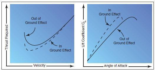
[Figure 3-8 wing in ground effect flight changes drag and lift]
Ground effect changes drag and lift. Ground effect also will alter the thrust required versus velocity. Since induced drag predominates at low speeds, the reduction of induced drag due to ground effect will cause the most significant reduction of thrust required (parasite plus induced drag) at low speeds.
The reduction in induced flow due to ground effect causes a significant reduction in induced drag but causes no direct effect on parasite drag. As a result of the reduction in induced drag, the thrust required at low speeds will be reduced.
Due to the change in upwash, downwash, and wingtip vortices, there may be a change in position (installation) error of the airspeed system, associated with ground effect. In the majority of cases, ground effect will cause an increase in the local pressure at the static source and produce a lower indication of airspeed and altitude. Thus, the airplane may be airborne at an indicated airspeed less than that normally required.
In order for ground effect to be of significant magnitude, the wing must be quite close to the ground. One of the direct results of ground effect is the variation of induced drag with wing height above the ground at a constant lift coefficient. When the wing is at a height equal to its span, the reduction in induced drag is only 1.4 percent. However, when the wing is at a height equal to one-fourth its span, the reduction in induced drag is 23.5 percent and, when the wing is at a height equal to one-tenth its span, the reduction in induced drag is 47.6 percent. Thus, a large reduction in induced drag will take place only when the wing is very close to the ground. Because of this variation, ground effect is most usually recognized during the liftoff for takeoff or just prior to touchdown when landing.
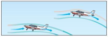
During the takeoff phase of flight, ground effect produces some important relationships. The airplane leaving ground effect after takeoff encounters just the reverse of the airplane entering ground effect during landing; i.e., the airplane leaving ground effect will:
• Require an increase in angle of attack to maintain the same lift coefficient.
• Experience an increase in induced drag and thrust required.
• Experience a decrease in stability and a nose-up change in moment.
• Produce a reduction in static source pressure and increase in indicated airspeed.
These general effects should point out the possible danger in attempting takeoff prior to achieving the recommended takeoff speed. Due to the reduced drag in ground effect, the airplane may seem capable of takeoff well below the recommended speed. However, as the airplane rises out of ground effect with a deficiency of speed, the greater induced drag may result in very marginal initial climb performance. In the extreme conditions such as high gross weight, high density altitude, and high temperature, a deficiency of airspeed during takeoff may permit the airplane to become airborne but be incapable of flying out of ground effect. In this case, the airplane may become airborne initially with a deficiency of speed, and then settle back to the runway. It is important that no attempt be made to force the airplane to become airborne with a deficiency of speed; the recommended takeoff speed is necessary to provide adequate initial climb performance. For this reason, it is imperative that a definite climb be established before retracting the landing gear or flaps.
During the landing phase of flight, the effect of proximity to the ground also must be understood and appreciated. If the airplane is brought into ground effect with a constant angle of attack, the airplane will experience an increase in lift coefficient and a reduction in the thrust required. Hence, a “floating” effect may occur. Because of the reduced drag and power off deceleration in ground effect, any excess speed at the point of flare may incur a considerable “float” distance. As the airplane nears the point of touchdown, ground effect will be most realized at altitudes less than the wingspan. During the final phases of the approach as the airplane nears the ground, a reduced power setting is necessary or the reduced thrust required would allow the airplane to climb above the desired glidepath.
AXES OF AN AIRPLANE
Whenever an airplane changes its flight attitude or position in flight, it rotates about one or more of three axes, which are imaginary lines that pass through the airplane’s center of gravity. The axes of an airplane can be considered as imaginary axles around which the airplane turns, much like the axle around which a wheel rotates. At the point where all three axes intersect, each is at a 90° angle to the other two. The axis, which extends lengthwise through the fuselage from the nose to the tail, is the longitudinal axis. The axis, which extends crosswise from wingtip to wingtip, is the lateral axis. The axis, which passes vertically through the center of gravity, is the vertical axis.
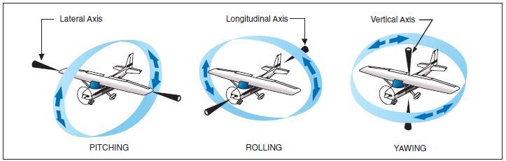
[Figure 3-9 Axes of an airplane]
The airplane’s motion about its longitudinal axis resembles the roll of a ship from side to side. In fact, the names used in describing the motion about an airplane’s three axes were originally nautical terms. They have been adapted to aeronautical terminology because of the similarity of motion between an airplane and the seagoing ship. In light of the adoption of nautical terms, the motion about the airplane’s longitudinal axis is called “roll”; motion about its lateral axis is referred to as “pitch.” Finally, an airplane moves about its vertical axis in a motion, which is termed “yaw”—that is, a horizontal (left and right) movement of the airplane’s nose. The three motions of the airplane (roll, pitch, and yaw) are controlled by three control surfaces. Roll is controlled by the ailerons; pitch is controlled by the elevators; yaw is controlled by the rudder. The use of these controls is explained in Flight Controls page.
MOMENTS AND MOMENT ARM
A study of physics shows that a body that is free to rotate will always turn about its center of gravity. In aerodynamic terms, the mathematical measure of an airplane’s tendency to rotate about its center of gravity is called a “moment.” A moment is said to be equal to the product of the force applied and the distance at which the force is applied. (A moment arm is the distance from a datum [reference point or line] to the applied force.) For airplane weight and balance computations, “moments” are expressed in terms of the distance of the arm times the airplane’s weight, or simply, inch pounds.
Airplane designers locate the fore and aft position of the airplane’s center of gravity as nearly as possible to the 20 percent point of the mean aerodynamic chord (MAC). If the thrust line is designed to pass horizontally through the center of gravity, it will not cause the airplane to pitch when power is changed, and there will be no difference in moment due to thrust for a power-on or power-off condition of flight. Although designers have some control over the location of the drag forces, they are not always able to make the resultant drag forces pass through the center of gravity of the airplane. However, the one item over which they have the greatest control is the size and location of the tail. The objective is to make the moments (due to thrust, drag, and lift) as small as possible; and, by proper location of the tail, to provide the means of balancing the airplane longitudinally for any condition of flight.
The pilot has no direct control over the location of forces acting on the airplane in flight, except for controlling the center of lift by changing the angle of attack. Such a change, however, immediately involves changes in other forces. Therefore, the pilot cannot independently change the location of one force without changing the effect of others. For example, a change in airspeed involves a change in lift, as well as a change in drag and a change in the up or down force on the tail. As forces such as turbulence and gusts act to displace the airplane, the pilot reacts by providing opposing control forces to counteract this displacement.
Some airplanes are subject to changes in the location of the center of gravity with variations of load. Trimming devices are used to counteract the forces set up by fuel burnoff, and loading or off-loading of passengers or cargo. Elevator trim tabs and adjustable horizontal stabilizers comprise the most common devices provided to the pilot for trimming for load variations. Over the wide ranges of balance during flight in large airplanes, the force which the pilot has to exert on the controls would become excessive and fatiguing if means of trimming were not provided.
DESIGN CHARACTERISTICS
Every pilot who has flown numerous types of airplanes has noted that each airplane handles somewhat differently—that is, each resists or responds to control pressures in its own way. A training type airplane is quick to respond to control applications while a transport airplane usually feels heavy on the controls and responds to control pressures more slowly. These features can be designed into an airplane to facilitate the particular purpose the airplane is to fulfill by considering certain stability and maneuvering requirements. In the following discussion, it is intended to summarize the more important aspects of an airplane’s stability; its maneuvering and controllability qualities; how they are analyzed; and their relationship to various flight conditions. In brief, the basic differences between stability, maneuverability, and controllability are as follows:
• Stability—The inherent quality of an airplane to correct for conditions that may disturb its equilibrium, and to return or to continue on the original flightpath. It is primarily an airplane design characteristic.
• Maneuverability—The quality of an airplane that permits it to be maneuvered easily and to withstand the stresses imposed by maneuvers. It is governed by the airplane’s weight, inertia, size and location of flight controls, structural strength, and powerplant. It too is an airplane design characteristic.
• Controllability—The capability of an airplane to respond to the pilot’s control, especially with regard to flightpath and attitude. It is the quality of the airplane’s response to the pilot’s control application when maneuvering the airplane, regardless of its stability characteristics.
BASIC CONCEPTS OF STABILITY
The flightpaths and attitudes in which an airplane can fly are limited only by the aerodynamic characteristics of the airplane, its propulsive system, and its structural strength. These limitations indicate the maximum performance and maneuverability of the airplane. If the airplane is to provide maximum utility, it must be safely controllable to the full extent of these limits without exceeding the pilot’s strength or requiring exceptional flying ability. If an airplane is to fly straight and steady along any arbitrary flightpath, the forces acting on it must be in static equilibrium. The reaction of any body when its equilibrium is disturbed is referred to as stability. There are two types of stability; static and dynamic. Static will be discussed first, and in this discussion the following definitions will apply:
• Equilibrium—All opposing forces acting on the airplane are balanced; (i.e., steady, unaccelerated flight conditions).
• Static Stability—The initial tendency that the airplane displays after its equilibrium is disturbed.
• Positive Static Stability—The initial tendency of the airplane to return to the original state of equilibrium after being disturbed.
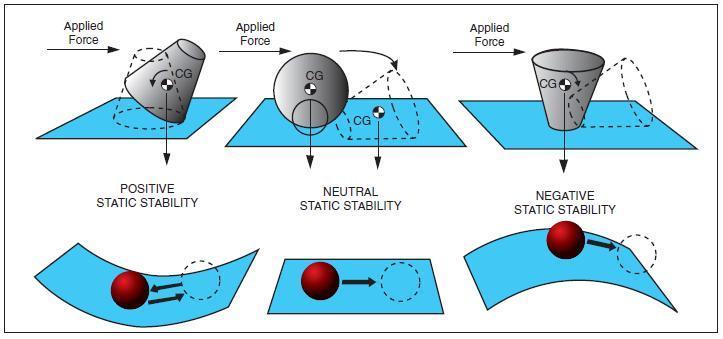
[Figure 3-10 Types of airplane stability]
• Negative Static Stability—The initial tendency of the airplane to continue away from the original state of equilibrium after being disturbed.
• Neutral Static Stability—The initial tendency of the airplane to remain in a new condition after its equilibrium has been disturbed.
STATIC STABILITY
Stability of an airplane in flight is slightly more complex than just explained, because the airplane is free to move in any direction and must be controllable in pitch, roll, and direction. When designing the airplane, engineers must compromise between stability, maneuverability, and controllability; and the problem is compounded because of the airplane’s three-axis freedom. Too much stability is detrimental to maneuverability, and similarly, not enough stability is detrimental to controllability. In the design of airplanes, compromise between the two is the keyword.
DYNAMIC STABILITY
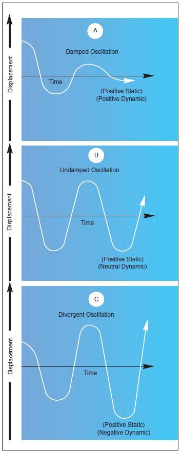
[Figure 3-11. Damped versus undamped stability]
Static stability has been defined as the initial tendency that the airplane displays after being disturbed from its trimmed condition. Occasionally, the initial tendency is different or opposite from the overall tendency, so distinction must be made between the two. Dynamic stability is the overall tendency that the airplane displays after its equilibrium is disturbed. The curves of figure 3-11 represent the variation of controlled functions versus time. It is seen that the unit of time is very significant. If the time unit for one cycle or oscillation is above 10 seconds’ duration, it is called a “long-period” oscillation (phugoid) and is easily controlled. In a longitudinal phugoid oscillation, the angle of attack remains constant when the airspeed increases and decreases. To a certain degree, a convergent phugoid is desirable but is not required. The phugoid can be determined only on a statically stable airplane, and this has a great effect on the trimming qualities of the airplane. If the time unit for one cycle or oscillation is less than one or two seconds, it is called a “short-period” oscillation and is normally very difficult, if not impossible, for the pilot to control. This is the type of oscillation that the pilot can easily “get in phase with” and reinforce.
A neutral or divergent, short-period oscillation is dangerous because structural failure usually results if the oscillation is not damped immediately. Short-period oscillations affect airplane and control surfaces alike and reveal themselves as “porpoising” in the airplane, or as in “buzz” or “flutter” in the control surfaces. Basically, the short-period oscillation is a change in angle of attack with no change in airspeed. A short-period oscillation of a control surface is usually of such high frequency that the airplane does not have time to react. Logically, the Code of Federal Regulations require that short-period oscillations be heavily damped (i.e., die out immediately). Flight tests during the airworthiness certification of airplanes are conducted for this condition by inducing the oscillation in the controls for pitch, roll, or yaw at the most critical speed (i.e., at VNE, the never-exceed speed). The test pilot strikes the control wheel or rudder pedal a sharp blow and observes the results.
LONGITUDINAL STABILITY (PITCHING)
In designing an airplane, a great deal of effort is spent in developing the desired degree of stability around all three axes. But longitudinal stability about the lateral axis is considered to be the most affected by certain variables in various flight conditions.
Longitudinal stability is the quality that makes an airplane stable about its lateral axis. It involves the pitching motion as the airplane’s nose moves up and down in flight. Alongitudinally unstable airplane has a tendency to dive or climb progressively into a very steep dive or climb, or even a stall. Thus, an airplane with longitudinal instability becomes difficult and sometimes dangerous to fly. Static longitudinal stability or instability in an airplane, is dependent upon three factors:
1. Location of the wing with respect to the center of gravity;
2. Location of the horizontal tail surfaces with respect to the center of gravity; and
3. The area or size of the tail surfaces.
In analyzing stability, it should be recalled that a body that is free to rotate will always turn about its center of gravity.
To obtain static longitudinal stability, the relation of the wing and tail moments must be such that, if the moments are initially balanced and the airplane is suddenly nosed up, the wing moments and tail moments will change so that the sum of their forces will provide an unbalanced but restoring moment which, in turn, will bring the nose down again. Similarly, if the airplane is nosed down, the resulting change in moments will bring the nose back up.
The center of lift, sometimes called the center of pressure, in most unsymmetrical airfoils has a tendency to change its fore and aft position with a change in the angle of attack. The center of pressure tends to move forward with an increase in angle of attack and to move aft with a decrease in angle of attack. This means that when the angle of attack of an airfoil is increased, the center of pressure (lift) by moving forward, tends to lift the leading edge of the wing still more. This tendency gives the wing an inherent quality of instability.
[Figure 3-12. Longitudinal stability.]
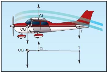
Figure 3-12 shows an airplane in straight-and-level flight. The line CG-CL-T represents the airplane’s longitudinal axis from the center of gravity (CG) to a point T on the horizontal stabilizer. The center of lift (or center of pressure) is represented by the point CL.
Most airplanes are designed so that the wing’s center of lift (CL) is to the rear of the center of gravity. This makes the airplane “nose heavy” and requires that there be a slight downward force on the horizontal stabilizer in order to balance the airplane and keep the nose from continually pitching downward. Compensation for this nose heaviness is provided by setting the horizontal stabilizer at a slight negative angle of attack. The downward force thus produced, holds the tail down, counterbalancing the “heavy” nose. It is as if the line CG-CL-T was a lever with an upward force at CL and two downward forces balancing each other, one a strong force at the CG point and the other, a much lesser force, at point T (downward air pressure on the stabilizer). Applying simple physics principles, it can be seen that if an iron bar were suspended at point CL with a heavy weight hanging on it at the CG, it would take some downward pressure at point T to keep the “lever” in balance.
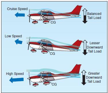
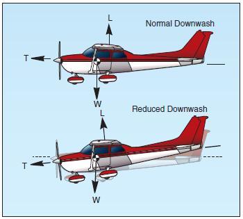
Even though the horizontal stabilizer may be level when the airplane is in level flight, there is a downwash of air from the wings. This downwash strikes the top of the stabilizer and produces a downward pressure, which at a certain speed will be just enough to balance the “lever.” The faster the airplane is flying, the greater this downwash and the greater the downward force on the horizontal stabilizer (except “T” tails).
[Figure 3-13 Effect of speed on wing downwash]
In airplanes with fixed position horizontal stabilizers, the airplane manufacturer sets the stabilizer at an angle that will provide the best stability (or balance) during flight at the design cruising speed and power setting.
[Figure 3-14 Reduced power allows pitch down]
If the airplane’s speed decreases, the speed of the airflow over the wing is decreased. As a result of this decreased flow of air over the wing, the downwash is reduced, causing a lesser downward force on the horizontal stabilizer. In turn, the characteristic nose heaviness is accentuated, causing the airplane’s nose to pitch down more. This places the airplane in a nose-low attitude, lessening the wing’s angle of attack and drag and allowing the airspeed to increase. As the airplane continues in the nose-low attitude and its speed increases, the downward force on the horizontal stabilizer is once again increased.
Consequently, the tail is again pushed downward and the nose rises into a climbing attitude.
As this climb continues, the airspeed again decreases, causing the downward force on the tail to decrease until the nose lowers once more. However, because the airplane is dynamically stable, the nose does not lower as far this time as it did before. The airplane will acquire enough speed in this more gradual dive to start it into another climb, but the climb is not so steep as the preceding one.
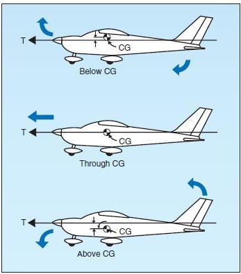
After several of these diminishing oscillations, in which the nose alternately rises and lowers, the airplane will finally settle down to a speed at which the downward force on the tail exactly counteracts the tendency of the airplane to dive. When this condition is attained, the airplane will once again be in balanced flight and will continue in stabilized flight as long as this attitude and airspeed are not changed. A similar effect will be noted upon closing the throttle. The downwash of the wings is reduced and the force at T in figure 3-12 is not enough to hold the horizontal stabilizer down. It is as if the force at T on the lever were allowing the force of gravity to pull the nose down. This, of course, is a desirable characteristic because the airplane is inherently trying to regain airspeed and reestablish the proper balance. Power or thrust can also have a destabilizing effect in that an increase of power may tend to make the nose rise. The airplane designer can offset this by establishing a “high thrustline” wherein the line of thrust passes above the center of gravity.
[Figures 3-15 Thrust line affects longitudinal stability]
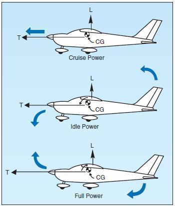
[Figures 3-16 Power changes affect longitudinal stability]
In this case, as power or thrust is increased a moment is produced to counteract the down load on the tail. On the other hand, a very “low thrust line” would tend to add to the nose-up effect of the horizontal tail surface. Figure 3-15. Thrust line affects longitudinal stability.
It can be concluded, then, that with the center of gravity forward of the center of lift, and with an aerodynamic tail-down force, the result is that the airplane always tries to return to a safe flying attitude.
A simple demonstration of longitudinal stability may be made as follows: Trim the airplane for “hands off” control in level flight. Then momentarily give the controls a slight push to nose the airplane down. If, within a brief period, the nose rises to the original position and then stops, the airplane is statically stable. Ordinarily, the nose will pass the original position (that of level flight) and a series of slow pitching oscillations will follow. If the oscillations gradually cease, the airplane has positive stability; if they continue unevenly, the airplane has neutral stability; if they increase, the airplane is unstable.
LATERAL STABILITY (ROLLING)
Stability about the airplane’s longitudinal axis, which extends from nose to tail, is called lateral stability. This helps to stabilize the lateral or rolling effect when one wing gets lower than the wing on the opposite side of the airplane. There are four main design factors that make an airplane stable laterally: dihedral, keel effect, sweepback, and weight distribution.
The most common procedure for producing lateral stability is to build the wings with a dihedral angle varying from one to three degrees. In other words, the wings on either side of the airplane join the fuselage to form a slight V or angle called “dihedral,” and this is measured by the angle made by each wing above a line parallel to the lateral axis.
The basis of rolling stability is, of course, the lateral balance of forces produced by the airplane’s wings. Any imbalance in lift results in a tendency for the airplane to roll about its longitudinal axis. Stated another way, dihedral involves a balance of lift created by the wings’ angle of attack on each side of the airplane’s longitudinal axis.
If a momentary gust of wind forces one wing of the airplane to rise and the other to lower, the airplane will bank. When the airplane is banked without turning, it tends to sideslip or slide downward toward the lowered wing.
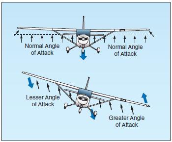
[Figure 3-17 Dihedral for lateral stability.]
Since the wings have dihedral, the air strikes the low wing at much greater angle of attack than the high wing. This increases the lift on the low wing and decreases lift on the high wing, and tends to restore the airplane to its original lateral attitude (wings level)—that is, the angle of attack and lift on the two wings are again equal. Figure 3-17. Dihedral for lateral stability. The effect of dihedral, then, is to produce a rolling moment tending to return the airplane to a laterally balanced flight condition when a sideslip occurs.
The restoring force may move the low wing up too far, so that the opposite wing now goes down. If so, the process will be repeated, decreasing with each lateral oscillation until a balance for wings-level flight is finally reached.
Conversely, excessive dihedral has an adverse effect on lateral maneuvering qualities. The airplane may be so stable laterally that it resists any intentional rolling motion. For this reason, airplanes that require fast roll or banking characteristics usually have less dihedral than those designed for less maneuverability.
The contribution of sweepback to dihedral effect is important because of the nature of the contribution. In a sideslip, the wing into the wind is operating with an effective decrease in sweepback, while the wing out of the wind is operating with an effective increase in sweepback. The swept wing is responsive only to the wind component that is perpendicular to the wing’s leading edge. Consequently, if the wing is operating at a positive lift coefficient, the wing into the wind has an increase in lift, and the wing out of the wind has a decrease in lift. In this manner, the swept back wing would contribute a positive dihedral effect and the swept forward wing would contribute a negative dihedral effect.
During flight, the side area of the airplane’s fuselage and vertical fin react to the airflow in much the same manner as the keel of a ship. That is, it exerts a steadying influence on the airplane laterally about the longitudinal axis. Such laterally stable airplanes are constructed so that the greater portion of the keel area is above and behind the center of gravity.
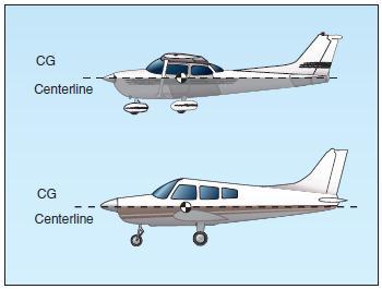
[Figure 3-18 Keel area for lateral stability]
Thus, when the airplane slips to one side, the combination of the airplane’s weight and the pressure of the airflow against the upper portion of the keel area (both acting about the CG) tends to roll the airplane back to wings-level flight. Figure 3-18. Keel area for lateral stability.
VERTICAL STABILITY (YAWING)
Stability about the airplane’s vertical axis (the sideways moment) is called yawing or directional stability. Yawing or directional stability is the more easily achieved stability in airplane design. The area of the vertical fin and the sides of the fuselage aft of the center of gravity are the prime contributors which make the airplane act like the well known weathervane or arrow, pointing its nose into the relative wind. In examining a weathervane, it can be seen that if exactly the same amount of surface were exposed to the wind in front of the pivot point as behind it, the forces fore and aft would be in balance and little or no directional movement would result. Consequently, it is necessary to have a greater surface aft of the pivot point that forward of it. Similarly in an airplane, the designer must ensure positive directional stability by making the side surface greater aft than ahead of the center of gravity.
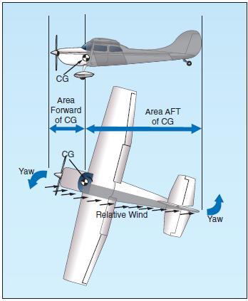
[Figure 3-19 Fuselage and fin for vertical stability]
To provide more positive stability aside from that provided by the fuselage, a vertical fin is added. The fin acts similar to the feather on an arrow in maintaining straight flight. Like the weathervane and the arrow, the farther aft this fin is placed and the larger its size, the greater the airplane’s directional stability.
If an airplane is flying in a straight line, and a sideward gust of air gives the airplane a slight rotation about its vertical axis (i.e., the right), the motion is retarded and stopped by the fin because while the airplane is rotating to the right, the air is striking the left side of the fin at an angle. This causes pressure on the left side of the fin, which resists the turning motion and slows down the airplane’s yaw. In doing so, it acts somewhat like the weathervane by turning the airplane into the relative wind. The initial change in direction of the airplane’s flightpath is generally slightly behind its change of heading. Therefore, after a slight yawing of the airplane to the right, there is a brief moment when the airplane is still moving along its original path, but its longitudinal axis is pointed slightly to the right.
The airplane is then momentarily skidding sideways, and during that moment (since it is assumed that although the yawing motion has stopped, the excess pressure on the left side of the fin still persists) there is necessarily a tendency for the airplane to be turned partially back to the left. That is, there is a momentary restoring tendency caused by the fin.
This restoring tendency is relatively slow in developing and ceases when the airplane stops skidding. When it ceases, the airplane will be flying in a direction slightly different from the original direction. In other words, it will not of its own accord return to the original heading; the pilot must reestablish the initial heading.
A minor improvement of directional stability may be obtained through sweepback. Sweepback is incorporated in the design of the wing primarily to delay the onset of compressibility during high-speed flight. In lighter and slower airplanes, sweepback aids in locating the center of pressure in the correct relationship with the center of gravity. Alongitudinally stable airplane is built with the center of pressure aft of the center of gravity.
Because of structural reasons, airplane designers sometimes cannot attach the wings to the fuselage at the exact desired point. If they had to mount the wings too far forward, and at right angles to the fuselage, the center of pressure would not be far enough to the rear to result in the desired amount of longitudinal stability. By building sweepback into the wings, however, the designers can move the center of pressure toward the rear. The amount of sweepback and the position of the wings then place the center of pressure in the correct location.
The contribution of the wing to static directional stability is usually small. The swept wing provides a stable contribution depending on the amount of sweepback, but the contribution is relatively small when compared with other components.
FREE DIRECTIONAL OSCILLATIONS (DUTCH ROLL)
Dutch Roll is a coupled lateral/directional oscillation that is usually dynamically stable but is objectionable in an airplane because of the oscillatory nature. The damping of the oscillatory mode may be weak or strong depending on the properties of the particular airplane.
Unfortunately all air is not smooth. There are bumps and depressions created by gusty updrafts and downdrafts, and by gusts from ahead, behind, or the side of the airplane.
The response of the airplane to a disturbance from equilibrium is a combined rolling/yawing oscillation in which the rolling motion is phased to precede the yawing motion. The yawing motion is not too significant, but the roll is much more noticeable. When the airplane rolls back toward level flight in response to dihedral effect, it rolls back too far and sideslips the other way. Thus, the airplane overshoots each time because of the strong dihedral effect. When the dihedral effect is large in comparison with static directional stability, the Dutch Roll motion has weak damping and is objectionable. When the static directional stability is strong in comparison with the dihedral effect, the Dutch Roll motion has such heavy damping that it is not objectionable. However, these qualities tend toward spiral instability.
The choice is then the least of two evils—Dutch Roll is objectionable and spiral instability is tolerable if the rate of divergence is low. Since the more important handling qualities are a result of high static directional stability and minimum necessary dihedral effect, most airplanes demonstrate a mild spiral tendency. This tendency would be indicated to the pilot by the fact that the airplane cannot be flown “hands off” indefinitely.
In most modern airplanes, except high-speed swept wing designs, these free directional oscillations usually die out automatically in a very few cycles unless the air continues to be gusty or turbulent. Those airplanes with continuing Dutch Roll tendencies usually are equipped with gyro stabilized yaw dampers. An airplane that has Dutch Roll tendencies is disconcerting, to say the least. Therefore, the manufacturer tries to reach a medium between too much and too little directional stability. Because it is more desirable for the airplane to have “spiral instability” than Dutch Roll tendencies, most airplanes are designed with that characteristic.
SPIRAL INSTABILITY
Spiral instability exists when the static directional stability of the airplane is very strong as compared to the effect of its dihedral in maintaining lateral equilibrium. When the lateral equilibrium of the airplane is disturbed by a gust of air and a sideslip is introduced, the strong directional stability tends to yaw the nose into the resultant relative wind while the comparatively weak dihedral lags in restoring the lateral balance. Due to this yaw, the wing on the outside of the turning moment travels forward faster than the inside wing and as a consequence, its lift becomes greater. This produces an overbanking tendency which, if not corrected by the pilot, will result in the bank angle becoming steeper and steeper. At the same time, the strong directional stability that yaws the airplane into the relative wind is actually forcing the nose to a lower pitch attitude. Then, the start of a slow downward spiral which has begun, if not counteracted by the pilot, will gradually increase into a steep spiral dive. Usually the rate of divergence in the spiral motion is so gradual that the pilot can control the tendency without any difficulty.
All airplanes are affected to some degree by this characteristic although they may be inherently stable in all other normal parameters. This tendency would be indicated to the pilot by the fact that the airplane cannot be flown “hands off” indefinitely.
Much study and effort has gone into development of control devices (wing leveler) to eliminate or at least correct this instability. Advanced stages of this spiral condition demand that the pilot be very careful in application of recovery controls, or excessive loads on the structure may be imposed. Of the in-flight structural failures that have occurred in general aviation airplanes, improper recovery from this condition has probably been the underlying cause of more fatalities than any other single factor. The reason is that the airspeed in the spiral condition builds up rapidly, and the application of back elevator force to reduce this speed and to pull the nose up only “tightens the turn,” increasing the load factor. The results of the prolonged uncontrolled spiral are always the same; either in-flight structural failure, crashing into the ground, or both. The most common causes on record for getting into this situation are: loss of horizon reference, inability of the pilot to control the airplane by reference to instruments, or a combination of both.
AERODYNAMIC FORCES IN FLIGHT MANEUVERS
FORCES IN TURNS
[Figure 3-20. Forces during normal coordinated turn.]
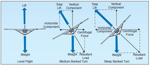
If an airplane were viewed in straight - and - level flight from the rear, and if the forces acting on the airplane actually could be seen, two forces (lift and weight) would be apparent, and if the airplane were in a bank it would be apparent that lift did not act directly opposite to the weight—it now acts in the direction of the bank. The fact that when the airplane banks, lift acts inward toward the center of the turn, as well as upward, is one of the basic truths to remember in the consideration of turns.
An object at rest or moving in a straight line will remain at rest or continue to move in a straight line until acted on by some other force. An airplane, like any moving object, requires a sideward force to make it turn. In a normal turn, this force is supplied by banking the airplane so that lift is exerted inward as well as upward. The force of lift during a turn is separated into two components at right angles to each other. One component, which acts vertically and opposite to the weight (gravity), is called the “vertical component of lift.” The other, which acts horizontally toward the center of the turn, is called the “horizontal component of lift,” or centripetal force. The horizontal component of lift is the force that pulls the airplane from a straight flightpath to make it turn. Centrifugal force is the “equal and opposite reaction” of the airplane to the change in direction and acts equal and opposite to the horizontal component of lift. This explains why, in a correctly executed turn, the force that turns the airplane is not supplied by the rudder.
An airplane is not steered like a boat or an automobile; in order for it to turn, it must be banked. If the airplane is not banked, there is no force available that will cause it to deviate from a straight flightpath. Conversely, when an airplane is banked, it will turn, provided it is not slipping to the inside of the turn. Good directional control is based on the fact that the airplane will attempt to turn whenever it is banked. This fact should be borne in mind at all times, particularly while attempting to hold the airplane in straight-and-level flight.
Merely banking the airplane into a turn produces no change in the total amount of lift developed. However, as was pointed out, the lift during the bank is divided into two components: one vertical and the other horizontal. This division reduces the amount of lift which is opposing gravity and actually supporting the airplane’s weight; consequently, the airplane loses altitude unless additional lift is created. This is done by increasing the angle of attack until the vertical component of lift is again equal to the weight. Since the vertical component of lift decreases as the bank angle increases, the angle of attack must be progressively increased to produce sufficient vertical lift to support the airplane’s weight. The fact that the vertical component of lift must be equal to the weight to maintain altitude is an important fact to remember when making constant altitude turns.
At a given airspeed, the rate at which an airplane turns depends upon the magnitude of the horizontal component of lift. It will be found that the horizontal component of lift is proportional to the angle of bank—that is, it increases or decreases respectively as the angle of bank increases or decreases. It logically follows then, that as the angle of bank is increased the horizontal component of lift increases, thereby increasing the rate of turn. Consequently, at any given airspeed the rate of turn can be controlled by adjusting the angle of bank.
To provide a vertical component of lift sufficient to hold altitude in a level turn, an increase in the angle of attack is required. Since the drag of the airfoil is directly proportional to its angle of attack, induced drag will increase as the lift is increased. This, in turn, causes a loss of airspeed in proportion to the angle of bank; a small angle of bank results in a small reduction in airspeed and a large angle of bank results in a large reduction in airspeed. Additional thrust (power) must be applied to prevent a reduction in airspeed in level turns; the required amount of additional thrust is proportional to the angle of bank.
To compensate for added lift, which would result if the airspeed were increased during a turn, the angle of attack must be decreased, or the angle of bank increased, if a constant altitude were to be maintained. If the angle of bank were held constant and the angle of attack decreased, the rate of turn would decrease. Therefore, in order to maintain a constant rate of turn as the airspeed is increased, the angle of attack must remain constant and the angle of bank increased.
It must be remembered that an increase in airspeed results in an increase of the turn radius and that centrifugal force is directly proportional to the radius of the turn. In a correctly executed turn, the horizontal component of lift must be exactly equal and opposite to the centrifugal force. Therefore, as the airspeed is increased in a constant rate level turn, the radius of the turn increases. This increase in the radius of turn causes an increase in the centrifugal force, which must be balanced by an increase in the horizontal component of lift, which can only be increased by increasing the angle of bank.
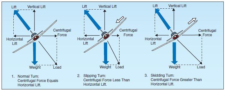
In a slipping turn, the airplane is not turning at the rate appropriate to the bank being used, since the airplane is yawed toward the outside of the turning flightpath. The airplane is banked too much for the rate of turn, so the horizontal lift component is greater than the centrifugal force.
[Figure 3-21 Normal, sloping, and skidding turns]
Equilibrium between the horizontal lift component and centrifugal force is reestablished either by decreasing the bank, increasing the rate of turn, or a combination of the two changes.
A skidding turn results from an excess of centrifugal force over the horizontal lift component, pulling the airplane toward the outside of the turn. The rate of turn is too great for the angle of bank. Correction of a skidding turn thus involves a reduction in the rate of turn, an increase in bank, or a combination of the two changes.
To maintain a given rate of turn, the angle of bank must be varied with the airspeed. This becomes particularly important in high-speed airplanes. For instance, at 400 miles per hour (m.p.h.), an airplane must be banked approximately 44° to execute a standard rate turn (3° per second). At this angle of bank, only about 79 percent of the lift of the airplane comprises the vertical component of the lift; the result is a loss of altitude unless the angle of attack is increased sufficiently to compensate for the loss of vertical lift.
FORCES IN CLIMBS
For all practical purposes, the wing’s lift in a steady state normal climb is the same as it is in a steady level flight at the same airspeed. Though the airplane’s flightpath has changed when the climb has been established, the angle of attack of the wing with respect to the inclined flightpath reverts to practically the same values, as does the lift. There is an initial momentary change, however, as shown in figure 3-22. During the transition from straight-and-level flight to a climb, a change in lift occurs when back elevator pressure is first applied. Raising the airplane’s nose increases the angle of attack and momentarily increases the lift. Lift at this moment is now greater than weight and starts the airplane climbing. After the flightpath is stabilized on the upward incline, the angle of attack and lift again revert to about the level flight values.
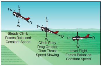
If the climb is entered with no change in power setting, the airspeed gradually diminishes because the thrust required to maintain a given airspeed in level flight is insufficient to maintain the same airspeed in a climb. When the flightpath is inclined upward, a component of the airplane’s weight acts in the same direction as, and parallel to, the total drag of the airplane, thereby increasing the total effective drag. Consequently, the total drag is greater than the power, and the airspeed decreases. The reduction in airspeed gradually results in a corresponding decrease in drag until the total drag (including the component of weight acting in the same direction) equals the thrust.
[Figure 3-23 Changes in speed during climb entry.]
Due to momentum, the change in airspeed is gradual, varying considerably with differences in airplane size, weight, total drag, and other factors. Figure 3-23. Changes in speed during climb entry. Generally, the forces of thrust and drag, and lift and weight, again become balanced when the airspeed stabilizes but at a value lower than in straight-and-level flight at the same power setting. Since in a climb the airplane’s weight is not only acting downward but rearward along with drag, additional power is required to maintain the same airspeed as in level flight. The amount of power depends on the angle of climb. When the climb is established so steep that there is insufficient power available, a slower speed results. It will be seen then that the amount of reserve power determines the climb performance of the airplane.
FORCES IN DESCENTS
As in climbs, the forces acting on the airplane go through definite changes when a descent is entered from straight-and-level flight. The analysis here is that of descending at the same power as used in straight-and-level flight.
When forward pressure is applied to the elevator control to start descending, or the airplane’s nose is allowed to pitch down, the angle of attack is decreased and, as a result, the lift of the airfoil is reduced. This reduction in total lift and angle of attack is momentary and occurs during the time the flightpath changes downward. The change to a downward flightpath is due to the lift momentarily becoming less than the weight of the airplane as the angle of attack is reduced. This imbalance between lift and weight causes the airplane to follow a descending flightpath with respect to the horizontal flightpath of straight-and-level flight. When the flightpath is in a steady descent, the airfoil’s angle of attack again approaches the original value, and lift and weight will again become stabilized. From the time the descent is started until it is stabilized, the airspeed will gradually increase. This is due to a component of weight now acting forward along the flightpath, similar to the manner it acted rearward in a climb. The overall effect is that of increased power or thrust, which in turn causes the increase in airspeed associated with descending at the same power as used in level flight.
To descend at the same airspeed as used in straightand-level flight, obviously, the power must be reduced as the descent is entered. The component of weight acting forward along the flightpath will increase as the angle of rate of descent increases and conversely, will decrease as the angle of rate of descent decreases. Therefore, the amount of power reduction required for a descent at the same speed as cruise will be determined by the steepness of the descent.
STALLS
An airplane will fly as long as the wing is creating sufficient lift to counteract the load imposed on it. When the lift is completely lost, the airplane stalls.
Remember, the direct cause of every stall is an excessive angle of attack. There are any number of flight maneuvers which may produce an increase in the angle of attack, but the stall does not occur until the angle of attack becomes excessive.
It must be emphasized that the stalling speed of a particular airplane is not a fixed value for all flight situations. However, a given airplane will always stall at the same angle of attack regardless of airspeed, weight, load factor, or density altitude. Each airplane has a particular angle of attack where the airflow separates from the upper surface of the wing and the stall occurs. This critical angle of attack varies from 16° to 20° depending on the airplane’s design. But each airplane has only one specific angle of attack where the stall occurs.
There are three situations in which the critical angle of attack can be exceeded: in low-speed flying, in high-speed flying, and in turning flight.
The airplane can be stalled in straight-and-level flight by flying too slowly. As the airspeed is being decreased, the angle of attack must be increased to retain the lift required for maintaining altitude. The slower the airspeed becomes, the more the angle of attack must be increased. Eventually, an angle of attack is reached which will result in the wing not producing enough lift to support the airplane and it will start settling. If the airspeed is reduced further, the airplane will stall, since the angle of attack has exceeded the critical angle and the airflow over the wing is disrupted.
It must be reemphasized here that low speed is not necessary to produce a stall. The wing can be brought into an excessive angle of attack at any speed. For example, take the case of an airplane which is in a dive with an airspeed of 200 knots when suddenly the pilot pulls back sharply on the elevator control.
[Figure 3-24 Forces exerted when pulling out of a dive during an airplane stalls]
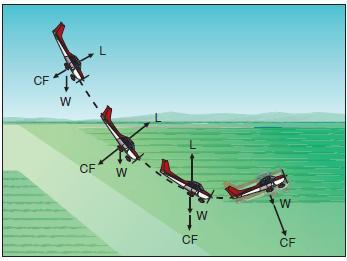
Because of gravity and centrifugal force, the airplane could not immediately alter its flightpath but would merely change its angle of attack abruptly from quite low to very high. Since the flightpath of the airplane in relation to the oncoming air determines the direction of the relative wind, the angle of attack is suddenly increased, and the airplane would quickly reach the stalling angle at a speed much greater than the normal stall speed. Figure 3-24. Forces exerted when pulling out of a dive. Similarly, the stalling speed of an airplane is higher in a level turn than in straight-and-level flight.
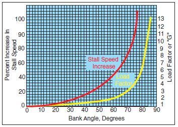
[Figure 3-25 Stall speed vs Wing Loading]
This is because centrifugal force is added to the airplane’s weight, and the wing must produce sufficient additional lift to counterbalance the load imposed by the combination of centrifugal force and weight. In a turn, the necessary additional lift is acquired by applying back pressure to the elevator control. This increases the wing’s angle of attack, and results in increased lift. The angle of attack must increase as the bank angle increases to counteract the increasing load caused by centrifugal force. If at any time during a turn the angle of attack becomes excessive, the airplane will stall.
At this point, the action of the airplane during a stall should be examined. To balance the airplane aerodynamically, the center of lift is normally located aft of the center of gravity. Although this makes the airplane inherently “nose heavy,” downwash on the horizontal stabilizer counteracts this condition. It can be seen then, that at the point of stall when the upward force of the wing’s lift and the downward tail force cease, an unbalanced condition exists. This allows the airplane to pitch down abruptly, rotating about its center of gravity. During this nose-down attitude, the angle of attack decreases and the airspeed again increases; hence, the smooth flow of air over the wing begins again, lift returns, and the airplane is again flying. However, considerable altitude may be lost before this cycle is complete.
BASIC PROPELLER PRINCIPLES
The airplane propeller consists of two or more blades and a central hub to which the blades are attached. Each blade of an airplane propeller is essentially a rotating wing. As a result of their construction, the propeller blades are like airfoils and produce forces that create the thrust to pull, or push, the airplane through the air. The power needed to rotate the propeller blades is furnished by the engine. The engine rotates the airfoils of the blades through the air at high speeds, and the propeller transforms the rotary power of the engine into forward thrust. An airplane moving through the air creates a drag force opposing its forward motion. Consequently, if an airplane is to fly, there must be a force applied to it that is equal to the drag, but acting forward. This force is called “thrust.”
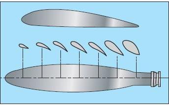
[Figure 3-26. Airfoil sections of propeller blade]
A cross section of a typical propeller blade is shown in figure 3-26. This section or blade element is an airfoil comparable to a cross section of an airplane wing. One surface of the blade is cambered or curved, similar to the upper surface of an airplane wing, while the other surface is flat like the bottom surface of a wing. The chord line is an imaginary line drawn through the blade from its leading edge to its trailing edge. As in a wing, the leading edge is the thick edge of the blade that meets the air as the propeller rotates. Figure 3-26. Airfoil sections of propeller blade. Blade angle, usually measured in degrees, is the angle between the chord of the blade and the plane of rotation and is measured at a specific point along the length of the blade. Because most propellers have a flat blade “face,” the chord line is often drawn along the face of the propeller blade. Pitch is not the same as blade angle, but because pitch is largely determined by blade angle, the two terms are often used interchangeably. An increase or decrease in one is usually associated with an increase or decrease in the other.
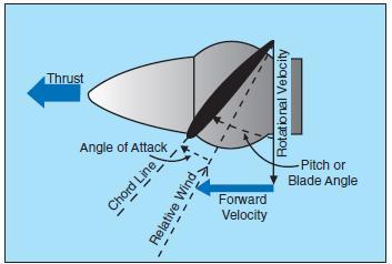
[Figure 3-27 Propeller blade angle measurement]
The pitch of a propeller may be designated in inches. A propeller designated as a “74-48” would be 74 inches in length and have an effective pitch of 48 inches. The pitch in inches is the distance which the propeller would screw through the air in one revolution if there were no slippage.
When specifying a fixed-pitch propeller for a new type of airplane, the manufacturer usually selects one with a pitch that will operate efficiently at the expected cruising speed of the airplane. Unfortunately, however, every fixed-pitch propeller must be a compromise, because it can be efficient at only a given combination of airspeed and r.p.m. Pilots do not have it within their power to change this combination in flight.
When the airplane is at rest on the ground with the engine operating, or moving slowly at the beginning of takeoff, the propeller efficiency is very low because the propeller is restrained from advancing with sufficient speed to permit its fixed-pitch blades to reach their full efficiency. In this situation, each propeller blade is turning through the air at an angle of attack that produces relatively little thrust for the amount of power required to turn it.
To understand the action of a propeller, consider first its motion, which is both rotational and forward. Thus, as shown by the vectors of propeller forces in figure 3-27, each section of a propeller blade moves downward and forward. The angle at which this air (relative wind) strikes the propeller blade is its angle of attack. The air deflection produced by this angle causes the dynamic pressure at the engine side of the propeller blade to be greater than atmospheric, thus creating thrust.
The shape of the blade also creates thrust, because it is cambered like the airfoil shape of a wing. Consequently, as the air flows past the propeller, the pressure on one side is less than that on the other. As in a wing, this produces a reaction force in the direction of the lesser pressure. In the case of a wing, the airflow over the wing has less pressure, and the force (lift) is upward. In the case of the propeller, which is mounted in a vertical instead of a horizontal plane, the area of decreased pressure is in front of the propeller, and the force (thrust) is in a forward direction. Aerodynamically, then, thrust is the result of the propeller shape and the angle of attack of the blade.
Another way to consider thrust is in terms of the mass of air handled by the propeller. In these terms, thrust is equal to the mass of air handled, times the slipstream velocity, minus the velocity of the airplane. The power expended in producing thrust depends on the rate of air mass movement. On the average, thrust constitutes approximately 80 percent of the torque (total horsepower absorbed by the propeller). The other 20 percent is lost in friction and slippage. For any speed of rotation, the horsepower absorbed by the propeller balances the horsepower delivered by the engine. For any single revolution of the propeller, the amount of air handled depends on the blade angle, which determines how big a “bite” of air the propeller takes. Thus, the blade angle is an excellent means of adjusting the load on the propeller to control the engine r.p.m.
The blade angle is also an excellent method of adjusting the angle of attack of the propeller. On constant- speed propellers, the blade angle must be adjusted to provide the most efficient angle of attack at all engine and airplane speeds. Lift versus drag curves, which are drawn for propellers as well as wings, indicate that the most efficient angle of attack is a small one varying from 2° to 4° positive. The actual blade angle necessary to maintain this small angle of attack varies with the forward speed of the airplane.
Fixed-pitch and ground-adjustable propellers are designed for best efficiency at one rotation and forward speed. They are designed for a given airplane and engine combination. A propeller may be used that provides the maximum propeller efficiency for either takeoff, climb, cruise, or high-speed flight. Any change in these conditions results in lowering the efficiency of both the propeller and the engine. Since the efficiency of any machine is the ratio of the useful power output to the actual power input, propeller efficiency is the ratio of thrust horsepower to brake horsepower. Propeller efficiency varies from 50 to 87 percent, depending on how much the propeller “slips.”
Propeller slip is the difference between the geometric pitch of the propeller and its effective pitch.
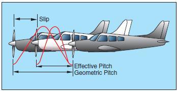
[Figure 3-28 Too Much Propeller Slip]
Geometric pitch is the theoretical distance a propeller should advance in one revolution; effective pitch is the distance it actually advances. Thus, geometric or theoretical pitch is based on no slippage, but actual or effective pitch includes propeller slippage in the air. Figure 3-28. Propeller slippage. The reason a propeller is “twisted” is that the outer parts of the propeller blades, like all things that turn about a central point, travel faster than the portions near the hub.
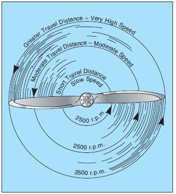
[Figure 3-29 Propeller tips travel faster than hubs]
If the blades had the same geometric pitch throughout their lengths, at cruise speed the portions near the hub could have negative angles of attack while the propeller tips would be stalled. “Twisting,” or variations in the geometric pitch of the blades, permits the propeller to operate with a relatively constant angle of attack along its length when in cruising flight. To put it another way, propeller blades are twisted to change the blade angle in proportion to the differences in speed of rotation along the length of the propeller and thereby keep thrust more nearly equalized along this length. Figure 3-29 show single blade propeller picture.
Usually 1° to 4° provides the most efficient lift/drag ratio, but in flight the propeller angle of attack of a fixed-pitch propeller will vary—normally from 0° to 15°. This variation is caused by changes in the relative airstream which in turn results from changes in airplane speed. In short, propeller angle of attack is the product of two motions: propeller rotation about its axis and its forward motion.
A constant-speed propeller, however, automatically keeps the blade angle adjusted for maximum efficiency for most conditions encountered in flight. During takeoff, when maximum power and thrust are required, the constant-speed propeller is at a low propeller blade angle or pitch. The low blade angle keeps the angle of attack small and efficient with respect to the relative wind. At the same time, it allows the propeller to handle a smaller mass of air per revolution. This light load allows the engine to turn at high r.p.m. and to convert the maximum amount of fuel into heat energy in a given time. The high r.p.m. also creates maximum thrust; for, although the mass of air handled per revolution is small, the number of revolutions per minute is many, the slipstream velocity is high, and with the low airplane speed, the thrust is maximum.
After liftoff, as the speed of the airplane increases, the constant-speed propeller automatically changes to a higher angle (or pitch). Again, the higher blade angle keeps the angle of attack small and efficient with respect to the relative wind. The higher blade angle increases the mass of air handled per revolution. This decreases the engine r.p.m., reducing fuel consumption and engine wear, and keeps thrust at a maximum.
After the takeoff climb is established in an airplane having a controllable-pitch propeller, the pilot reduces the power output of the engine to climb power by first decreasing the manifold pressure and then increasing the blade angle to lower the r.p.m.
At cruising altitude, when the airplane is in level flight and less power is required than is used in takeoff or climb, the pilot again reduces engine power by reducing the manifold pressure and then increasing the blade angle to decrease the r.p.m. Again, this provides a torque requirement to match the reduced engine power; for, although the mass of air handled per revolution is greater, it is more than offset by a decrease in slipstream velocity and an increase in airspeed. The angle of attack is still small because the blade angle has been increased with an increase in airspeed.
TORQUE AND P FACTOR
To the pilot, “torque” (the left turning tendency of the airplane) is made up of four elements which cause or produce a twisting or rotating motion around at least one of the airplane’s three axes. These four elements are:
1. Torque Reaction from Engine and Propeller.
2. Corkscrewing Effect of the Slipstream.
3. Gyroscopic Action of the Propeller.
4. Asymmetric Loading of the Propeller (P Factor).
TORQUE REACTION
Torque reaction involves Newton’s Third Law of Physics—for every action, there is an equal and opposite reaction. As applied to the airplane, this means that as the internal engine parts and propeller are revolving in one direction, an equal force is trying to rotate the airplane in the opposite direction.
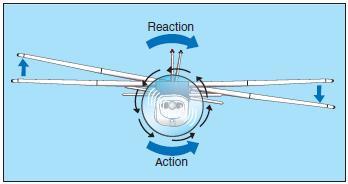
[Figure 3-30 Torque reaction]
Moderate Travel Distance – Moderate Speed Short Travel Distance Slow Speed Greater Travel Distance – Very High Speed 2500 r.p.m. 2500 r.p.m. 2500 r.p.m Figure 3-30.Torque reaction. When the airplane is airborne, this force is acting around the longitudinal axis, tending to make the airplane roll. To compensate for this, some of the older airplanes are rigged in a manner to create more lift on the wing that is being forced downward. The more modern airplanes are designed with the engine offset to counteract this effect of torque.
NOTE—Most United States built aircraft engines rotate the propeller clockwise, as viewed from the pilot’s seat.
The discussion here is with reference to those engines. Generally, the compensating factors are permanently set so that they compensate for this force at cruising speed, since most of the airplane’s operating lift is at that speed. However, aileron trim tabs permit further adjustment for other speeds.
When the airplane’s wheels are on the ground during the takeoff roll, an additional turning moment around the vertical axis is induced by torque reaction. As the left side of the airplane is being forced down by torque reaction, more weight is being placed on the left main landing gear. This results in more ground friction, or drag, on the left tire than on the right, causing a further turning moment to the left. The magnitude of this moment is dependent on many variables. Some of these variables are:
(1) size and horsepower of engine,
(2) size of propeller and the r.p.m.,
(3) size of the airplane, and
(4) condition of the ground surface.
This yawing moment on the takeoff roll is corrected by the pilot’s proper use of the rudder or rudder trim.
CORKSCREW EFFECT
The high-speed rotation of an airplane propeller gives a corkscrew or spiraling rotation to the slipstream. At high propeller speeds and low forward speed (as in the takeoffs and approaches to poweron stalls), this spiraling rotation is very compact and exerts a strong sideward force on the airplane’s vertical tail surface.
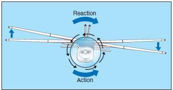
[Figure 3-31 Corkscrewing slipstream]
When this spiraling slipstream strikes the vertical fin on the left, it causes a left turning moment about the airplane’s vertical axis. The more compact the spiral, the more prominent this force is. As the forward speed increases, however, the spiral elongates and becomes less effective. The corkscrew flow of the slipstream also causes a rolling moment around the longitudinal axis. Note that this rolling moment caused by the corkscrew flow of the slipstream is to the right, while the rolling moment caused by torque reaction is to the left—in effect one may be counteracting the other. However, these forces vary greatly and it is up to the pilot to apply proper correction action by use of the flight controls at all times. These forces must be counteracted regardless of which is the most prominent at the time.
GYROSCOPIC ACTION
Before the gyroscopic effects of the propeller can be understood, it is necessary to understand the basic principle of a gyroscope.
All practical applications of the gyroscope are based upon two fundamental properties of gyroscopic action: rigidity in space and precession. The one of interest for this discussion is precession.
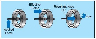
[Figure 3-32. Gyroscopic precession.]
Precession is the resultant action, or deflection, of a spinning rotor when a deflecting force is applied to its rim. As can be seen in figure 3-32, when a force is applied, the resulting force takes effect 90° ahead of and in the direction of rotation.
The rotating propeller of an airplane makes a very good gyroscope and thus has similar properties. Any time a force is applied to deflect the propeller out of its plane of rotation, the resulting force is 90° ahead of and in the direction of rotation and in the direction of application, causing a pitching moment, a yawing moment, or a combination of the two depending upon the point at which the force was applied.
This element of torque effect has always been associated with and considered more prominent in tailwheel-type airplanes, and most often occurs when the tail is being raised during the takeoff roll.
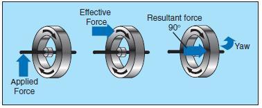
[Figure 3-33 Raising tail produces gyroscopic precession]
This change in pitch attitude has the same effect as applying a force to the top of the propeller’s plane of rotation. The resultant force acting 90° ahead causes a yawing moment to the left around the vertical axis. The magnitude of this moment depends on several variables, one of which is the abruptness with which the tail is raised (amount of force applied). However, precession, or gyroscopic action, occurs when a force is applied to any point on the rim of the propeller’s plane of rotation; the resultant force will still be 90° from the point of application in the direction of rotation. Depending on where the force is applied, the airplane is caused to yaw left or right, to pitch up or down, or a combination of pitching and yawing.
It can be said that as a result of gyroscopic action— any yawing around the vertical axis results in a pitching moment, and any pitching around the lateral axis results in a yawing moment.
To correct for the effect of gyroscopic action, it is necessary for the pilot to properly use elevator and rudder to prevent undesired pitching and yawing.
ASYMMETRIC LOADING (P FACTOR)
When an airplane is flying with a high angle of attack, the “bite” of the downward moving blade is greater than the “bite” of the upward moving blade; thus moving the center of thrust to the right of the prop disc area—causing a yawing moment toward the left around the vertical axis. That explanation is correct; however, to prove this phenomenon, it would be necessary to work wind vector problems on each blade, which gets quite involved when considering both the angle of attack of the airplane and the angle of attack of each blade.
This asymmetric loading is caused by the resultant velocity, which is generated by the combination of the velocity of the propeller blade in its plane of rotation and the velocity of the air passing horizontally through the propeller “disc.” With the airplane being flown at positive angles of attack, the right (viewed from the rear) or downswinging blade, is passing through an area of resultant velocity which is greater than that affecting the left or upswinging blade. Since the propeller blade is an airfoil, increased velocity means increased lift. Therefore, the downswinging blade having more “lift” tends to pull (yaw) the airplane’s nose to the left.
Simply stated, when the airplane is flying at a high angle of attack, the downward moving blade has a higher resultant velocity; therefore creating more lift than the upward moving blade.
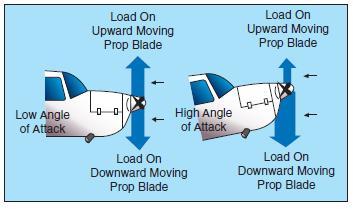
[Figure 3-34 Asymmetrical loading of propeller (P-factor)]
This might be easier to visualize if the propeller shaft was mounted perpendicular to the ground (like a helicopter). If there were no air movement at all, except that generated by the propeller itself, identical sections of each blade would have the same airspeed. However, with air moving horizontally across this vertically mounted propeller, the blade proceeding forward into the flow of air will have a higher airspeed than the blade retreating with the airflow. Thus, the blade proceeding into the horizontal airflow is creating more lift, or thrust, moving the center of thrust toward that blade. Visualize ROTATING the vertically mounted propeller shaft to shallower angles relative to the moving air (as on an airplane). This unbalanced thrust then becomes proportionately smaller and continues getting smaller until it reaches the value of zero when the propeller shaft is exactly horizontal in relation to the moving air.
Each of these four elements of torque effects vary in values with changes in flight situations. In one phase of flight, one of these elements may be more prominent than another; whereas, in another phase of flight, another element may be more prominent. The relationship of these values to each other will vary with different airplanes—depending on the AIRFRAME, ENGINE, AND PROPELLER combinations as well as other design features.
To maintain positive control of the airplane in all flight conditions, the pilot must apply the flight controls as necessary to compensate for these varying values.
LOAD FACTORS
The preceding sections only briefly considered some of the practical points of the principles of flight. To become a pilot, a detailed technical course in the science of aerodynamics is not necessary. However, with responsibilities for the safety of passengers, the competent pilot must have a well-founded concept of the forces which act on the airplane, and the advantageous use of these forces, as well as the operating limitations of the particular airplane. Any force applied to an airplane to deflect its flight from a straight line produces a stress on its structure; the amount of this force is termed “load factor.”
Aload factor is the ratio of the total airload acting on the airplane to the gross weight of the airplane. For example, a load factor of 3 means that the total load on an airplane’s structure is three times its gross weight. Load factors are usually expressed in terms of “G”—that is, a load factor of 3 may be spoken of as 3 G’s, or a load factor of 4 as 4 G’s.
It is interesting to note that in subjecting an airplane to 3 G’s in a pullup from a dive, one will be pressed down into the seat with a force equal to three times the person’s weight. Thus, an idea of the magnitude of the load factor obtained in any maneuver can be determined by considering the degree to which one is pressed down into the seat. Since the operating speed of modern airplanes has increased significantly, this effect has become so pronounced that it is a primary consideration in the design of the structure for all airplanes.
With the structural design of airplanes planned to withstand only a certain amount of overload, a knowledge of load factors has become essential for all pilots. Load factors are important to the pilot for two distinct reasons:
1. Because of the obviously dangerous overload that is possible for a pilot to impose on the airplane structures; and
2. Because an increased load factor increases the stalling speed and makes stalls possible at seemingly safe flight speeds.
LOAD FACTORS IN AIRPLANE DESIGN
The answer to the question “how strong should an airplane be” is determined largely by the use to which the airplane will be subjected. This is a difficult problem, because the maximum possible loads are much too high for use in efficient design. It is true that any pilot can make a very hard landing or an extremely sharp pullup from a dive, which would result in abnormal loads. However, such extremely abnormal loads must be dismissed somewhat if airplanes are built that will take off quickly, land slowly, and carry a worthwhile payload.
The problem of load factors in airplane design then reduces to that of determining the highest load factors that can be expected in normal operation under various operational situations. These load factors are called “limit load factors.” For reasons of safety, it is required that the airplane be designed to withstand these load factors without any structural damage. Although the Code of Federal Regulations requires that the airplane structure be capable of supporting one and one-half times these limit load factors without failure, it is accepted that parts of the airplane may bend or twist under these loads and that some structural damage may occur.
This 1.5 value is called the “factor of safety” and provides, to some extent, for loads higher than those expected under normal and reasonable operation. However, this strength reserve is not something which pilots should willfully abuse; rather it is there for their protection when they encounter unexpected conditions.
The above considerations apply to all loading conditions, whether they be due to gusts, maneuvers, or landings. The gust load factor requirements now in effect are substantially the same as those that have been in existence for years. Hundreds of thousands of operational hours have proven them adequate for safety. Since the pilot has little control over gust load factors (except to reduce the airplane’s speed when rough air is encountered), the gust loading requirements are substantially the same for most general aviation type airplanes regardless of their operational use. Generally, the gust load factors control the design of airplanes which are intended for strictly nonacrobatic usage.
An entirely different situation exists in airplane design with maneuvering load factors. It is necessary to discuss this matter separately with respect to:
(1) Airplanes which are designed in accordance with the Category System (i.e., Normal, Utility, Acrobatic); and
(2) Airplanes of older design which were built to requirements which did not provide for operational categories.
Airplanes designed under the Category System are readily identified by a placard in the cockpit, which states the operational category (or categories) in which the airplane is certificated. The maximum safe load factors (limit load factors) specified for airplanes in the various categories are as follows:
CATEGORY LIMIT LOAD
Normal* 3.8 to –1.52
Utility (mild acrobatics, including spins) 4.4 to –1.76
Acrobatic 6.0 to –3.0 1
*For airplanes with gross weight of more than 4,000 pounds, the limit load factor is reduced. To the limit loads given above, a safety factor of 50 percent is added.
There is an upward graduation in load factor with the increasing severity of maneuvers. The Category System provides for obtaining the maximum utility of an airplane. If normal operation alone is intended, the required load factor (and consequently the weight of the airplane) is less than if the airplane is to be employed in training or acrobatic maneuvers as they result in higher maneuvering loads.
Airplanes that do not have the category placard are designs that were constructed under earlier engineering requirements in which no operational restrictions were specifically given to the pilots. For airplanes of this type (up to weights of about 4,000 pounds) the required strength is comparable to present-day utility category airplanes, and the same types of operation are permissible. For airplanes of this type over 4,000 pounds, the load factors decrease with weight so that these airplanes should be regarded as being comparable to the normal category airplanes designed under the Category System, and they should be operated accordingly.
LOAD FACTORS IN STEEP TURNS
In a constant altitude, coordinated turn in any airplane, the load factor is the result of two forces: centrifugal force and gravity.
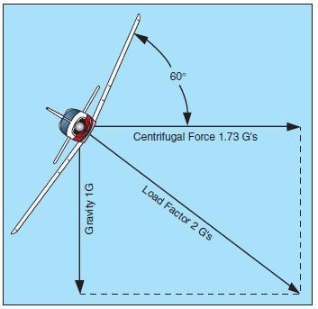
[Figure 3-35.Two forces cause load factor during turns.]
For any given bank angle, the rate of turn varies with the airspeed; the higher the speed, the slower the rate of turn. This compensates for added centrifugal force, allowing the load factor to remain the same.
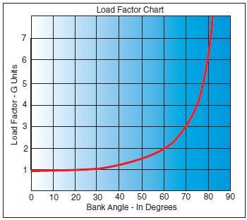
[Figure 3-36. Load factor with a bank angle]
Figure 3-36 reveals an important fact about turns— that the load factor increases at a terrific rate after a bank has reached 45° or 50°. The load factor for any airplane in a 60° bank is 2 G’s. The load factor in an 80° bank is 5.76 G’s. The wing must produce lift equal to these load factors if altitude is to be maintained.
It should be noted how rapidly the line denoting load factor rises as it approaches the 90° bank line, which it reaches only at infinity. The 90° banked, constant altitude turn mathematically is not possible. True, an airplane may be banked to 90° but not in a coordinated turn; an airplane which can be held in a 90° banked slipping turn is capable of straight knifeedged flight. At slightly more than 80°, the load factor exceeds the limit of 6 G’s, the limit load factor of an acrobatic airplane.
For a coordinated, constant altitude turn, the approximate maximum bank for the average general aviation airplane is 60°. This bank and its resultant necessary power setting reach the limit of this type of airplane. An additional 10° bank will increase the load factor by approximately 1 G, bringing it close to the yield point established for these airplanes.
LOAD FACTORS AND STALLING SPEEDS
Any airplane, within the limits of its structure, may be stalled at any airspeed. When a sufficiently high angle of attack is imposed, the smooth flow of air over an airfoil breaks up and separates, producing an abrupt change of flight characteristics and a sudden loss of lift, which results in a stall.
A study of this effect has revealed that the airplane’s stalling speed increases in proportion to the square root of the load factor. This means that an airplane with a normal unaccelerated stalling speed of 50 knots can be stalled at 100 knots by inducing a load factor of 4 G’s. If it were possible for this airplane to withstand a load factor of 9, it could be stalled at a speed of 150 knots. Therefore, a competent pilot should be aware of the following:
• The danger of inadvertently stalling the airplane by increasing the load factor, as in a steep turn or spiral; and
• That in intentionally stalling an airplane above its design maneuvering speed, a tremendous load factor is imposed.
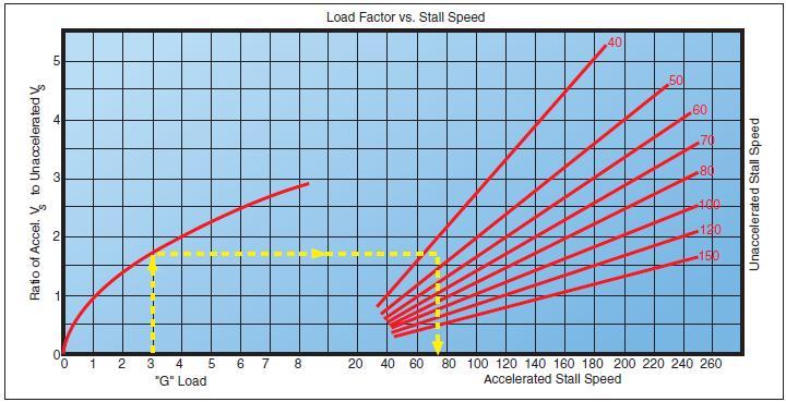
[Figure 3-37. Load factor changes stall speed.]
Reference to the charts in figures 3-36 and 3-37 will show that by banking the airplane to just beyond 72° in a steep turn produces a load factor of 3, and the stalling speed is increased significantly. If this turn is made in an airplane with a normal unaccelerated stalling speed of 45 knots, the airspeed must be kept above 75 knots to prevent inducing a stall. A similar effect is experienced in a quick pullup, or any maneuver producing load factors above 1 G. This has been the cause of accidents resulting from a sudden, unexpected loss of control, particularly in a steep turn or abrupt application of the back elevator control near the ground.
Since the load factor squares as the stalling speed doubles, it may be realized that tremendous loads may be imposed on structures by stalling an airplane at relatively high airspeeds.
The maximum speed at which an airplane may be stalled safely is now determined for all new designs. This speed is called the “design maneuvering speed” (VA) and is required to be entered in the FAA-approved Airplane Flight Manual or Pilot’s Operating Handbook (AFM/POH) of all recently designed airplanes. For older general aviation airplanes, this speed will be approximately 1.7 times the normal stalling speed. Thus, an older airplane which normally stalls at 60 knots must never be stalled at above 102 knots (60 knots x 1.7 = 102 knots). An airplane with a normal stalling speed of 60 knots will undergo, when stalled at 102 knots, a load factor equal to the square of the increase in speed or 2.89 G’s (1.7 x 1.7 = 2.89 G’s). (The above figures are an approximation to be considered as a guide and are not the exact answers to any set of problems. The design maneuvering speed should be determined from the particular airplane’s operating limitations when provided by the manufacturer.)
Since the leverage in the control system varies with different airplanes and some types employ “balanced” control surfaces while others do not, the pressure exerted by the pilot on the controls cannot be accepted as an index of the load factors produced in different airplanes. In most cases, load factors can be judged by the experienced pilot from the feel of seat pressure. They can also be measured by an instrument called an “accelerometer,” but since this instrument is not common in general aviation training airplanes, the development of the ability to judge load factors from the feel of their effect on the body is important. A knowledge of the principles outlined above is essential to the development of this ability to estimate load factors.
A thorough knowledge of load factors induced by varying degrees of bank, and the significance of design maneuvering speed (VA) will aid in the prevention of two of the most serious types of accidents:
1. Stalls from steep turns or excessive maneuvering near the ground; and
2. Structural failures during acrobatics or other violent maneuvers resulting from loss of control.
LOAD FACTORS AND FLIGHT MANEUVERS
Critical load factors apply to all flight maneuvers except unaccelerated straight flight where a load factor of 1 G is always present. Certain maneuvers considered in this section are known to involve relatively high load factors.
TURNS—Increased load factors are a characteristic of all banked turns. As noted in the section on load factors in steep turns and particularly figures 3-36 and 3-37, load factors become significant both to flight performance and to the load on wing structure as the bank increases beyond approximately 45°.
The yield factor of the average light plane is reached at a bank of approximately 70° to 75°, and the stalling speed is increased by approximately one-half at a bank of approximately 63°.
STALLS—The normal stall entered from straight level flight, or an unaccelerated straight climb, will not produce added load factors beyond the 1 G of straight-and-level flight. As the stall occurs, however, this load factor may be reduced toward zero, the factor at which nothing seems to have weight; and the pilot has the feeling of “floating free in space.” In the event recovery is effected by snapping the elevator control forward, negative load factors, those which impose a down load on the wings and raise the pilot from the seat, may be produced.
During the pullup following stall recovery, significant load factors sometimes are induced. Inadvertently these may be further increased during excessive diving (and consequently high airspeed) and abrupt pullups to level flight. One usually leads to the other, thus increasing the load factor. Abrupt pullups at high diving speeds may impose critical loads on airplane structures and may produce recurrent or secondary stalls by increasing the angle of attack to that of stalling.
As a generalization, a recovery from a stall made by diving only to cruising or design maneuvering airspeed, with a gradual pullup as soon as the airspeed is safely above stalling, can be effected with a load factor not to exceed 2 or 2.5 G’s. A higher load factor should never be necessary unless recovery has been effected with the airplane’s nose near or beyond the vertical attitude, or at extremely low altitudes to avoid diving into the ground.
SPINS—Since a stabilized spin is not essentially different from a stall in any element other than rotation, the same load factor considerations apply as those that apply to stall recovery. Since spin recoveries usually are effected with the nose much lower than is common in stall recoveries, higher airspeeds and consequently higher load factors are to be expected. The load factor in a proper spin recovery will usually be found to be about 2.5 G’s.
The load factor during a spin will vary with the spin characteristics of each airplane but is usually found to be slightly above the 1 G of level flight. There are two reasons this is true: 1. The airspeed in a spin is very low, usually within 2 knots of the unaccelerated stalling speeds; and 2. The airplane pivots, rather than turns, while it is in a spin.
HIGH-SPEED STALLS—The average light plane is not built to withstand the repeated application of load factors common to high-speed stalls. The load factor necessary for these maneuvers produces a stress on the wings and tail structure, which does not leave a reasonable margin of safety in most light airplanes.
The only way this stall can be induced at an airspeed above normal stalling involves the imposition of an added load factor, which may be accomplished by a severe pull on the elevator control. A speed of 1.7 times stalling speed (about 102 knots in a light airplane with a stalling speed of 60 knots) will produce a load factor of 3 G’s. Further, only a very narrow margin for error can be allowed for acrobatics in light airplanes. To illustrate how rapidly the load factor increases with airspeed, a high-speed stall at 112 knots in the same airplane would produce a load factor of 4 G’s.
CHANDELLES AND LAZY EIGHTS—It would be difficult to make a definite statement concerning load factors in these maneuvers as both involve smooth, shallow dives and pullups. The load factors incurred depend directly on the speed of the dives and the abruptness of the pullups.
Generally, the better the maneuver is performed, the less extreme will be the load factor induced. A chandelle or lazy eight, in which the pullup produces a load factor greater than 2 G’s will not result in as great a gain in altitude, and in low-powered airplanes it may result in a net loss of altitude.
The smoothest pullup possible, with a moderate load factor, will deliver the greatest gain in altitude in a chandelle and will result in a better overall performance in both chandelles and lazy eights. Further, it will be noted that recommended entry speed for these maneuvers is generally near the manufacturer’s design maneuvering speed, thereby allowing maximum development of load factors without exceeding the load limits.
ROUGH AIR—All certificated airplanes are designed to withstand loads imposed by gusts of considerable intensity. Gust load factors increase with increasing airspeed and the strength used for design purposes usually corresponds to the highest level flight speed. In extremely rough air, as in thunderstorms or frontal conditions, it is wise to reduce the speed to the design maneuvering speed. Regardless of the speed held, there may be gusts that can produce loads which exceed the load limits.
Most airplane flight manuals now include turbulent air penetration information. Operators of modern airplanes, capable of a wide range of speeds and altitudes, are benefited by this added feature both in comfort and safety. In this connection, it is to be noted that the maximum “never-exceed” placard dive speeds are determined for smooth air only. High-speed dives or acrobatics involving speed above the known maneuvering speed should never be practiced in rough or turbulent air.
In summary, it must be remembered that load factors induced by intentional acrobatics, abrupt pullups from dives, high-speed stalls, and gusts at high airspeeds all place added stress on the entire structure of an airplane.
Stress on the structure involves forces on any part of the airplane. There is a tendency for the uninformed to think of load factors only in terms of their effect on spars and struts. Most structural failures due to excess load factors involve rib structure within the leading and trailing edges of wings and tail group. The critical area of fabric-covered airplanes is the covering about one-third of the chord aft on the top surface of the wing.
The cumulative effect of such loads over a long period of time may tend to loosen and weaken vital parts so that actual failure may occur later when the airplane is being operated in a normal manner.
VG DIAGRAM
The flight operating strength of an airplane is presented on a graph whose horizontal scale is based on load factor.
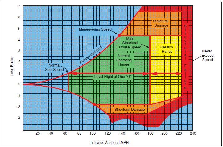
[Figure 3-38 Typical Vg diagram.]
The diagram is called a Vg diagram—velocity versus “g” loads or load factor. Each airplane has its own Vg diagram which is valid at a certain weight and altitude.
The lines of maximum lift capability (curved lines) are the first items of importance on the Vg diagram. The subject airplane in the illustration is capable of developing no more than one positive “g” at 62 m.p.h., the wing level stall speed of the airplane. Since the maximum load factor varies with the square of the airspeed, the maximum positive lift capability of this airplane is 2 “g” at 92 m.p.h., 3 “g” at 112 m.p.h., 4.4 “g” at 137 m.p.h., and so forth. Any load factor above this line is unavailable aerodynamically; i.e., the subject airplane cannot fly above the line of maximum lift capability (it will stall). Essentially the same situation exists for negative lift flight with the exception that the speed necessary to produce a given negative load factor is higher than that to produce the same positive load factor.
If the subject airplane is flown at a positive load factor greater than the positive limit load factor of 4.4, structural damage will be possible. When the airplane is operated in this region, objectionable permanent deformation of the primary structure may take place and a high rate of fatigue damage is incurred. Operation above the limit load factor must be avoided in normal operation.
There are two other points of importance on the Vg diagram. First, is the intersection of the positive limit load factor and the line of maximum positive lift capability. The airspeed at this point is the minimum airspeed at which the limit load can be developed aerodynamically. Any airspeed greater than this provides a positive lift capability sufficient to damage the airplane; any airspeed less does not provide positive lift capability sufficient to cause damage from excessive flight loads. The usual term given to this speed is “maneuvering speed,” since consideration of subsonic aerodynamics would predict minimum usable turn radius to occur at this condition. The maneuver speed is a valuable reference point, since an airplane operating below this point cannot produce a damaging positive flight load. Any combination of maneuver and gust cannot create damage due to excess airload when the airplane is below the maneuver speed.
Next, is the intersection of the negative limit load factor and line of maximum negative lift capability. Any airspeed greater than this provides a negative lift capability sufficient to damage the airplane; any airspeed less does not provide negative lift capability sufficient to damage the airplane from excessive flight loads.
The limit airspeed (or redline speed) is a design reference point for the airplane—the subject airplane is limited to 225 m.p.h. If flight is attempted beyond the limit airspeed, structural damage or structural failure may result from a variety of phenomena.
Thus, the airplane in flight is limited to a regime of airspeeds and g’s which do not exceed the limit (or redline) speed, do not exceed the limit load factor, and cannot exceed the maximum lift capability. The airplane must be operated within this “envelope” to prevent structural damage and ensure that the anticipated service lift of the airplane is obtained. The pilot must appreciate the Vg diagram as describing the allowable combination of airspeeds and load factors for safe operation. Any maneuver, gust, or gust plus maneuver outside the structural envelope can cause structural damage and effectively shorten the service life of the airplane.
WEIGHT AND BALANCE
Often a pilot regards the airplane’s weight and balance data as information of interest only to engineers, dispatchers, and operators of scheduled and nonscheduled air carriers. Along with this idea, the reasoning is that the airplane was weighed during the certification process and that this data is valid indefinitely, regardless of equipment changes or modifications. Further, this information is mistakenly reduced to a workable routine or “rule of thumb” such as: “If I have three passengers, I can load only 100 gallons of fuel; four passengers—70 gallons.”
Admittedly, this rule of thumb is adequate in many cases, but as the subject “Weight and Balance” suggests, the concern is not only with the weight of the airplane but also the location of its center of gravity (CG). The importance of the CG should have become apparent in the discussion of stability, controllability, and performance. If all pilots understood and respected the effect of CG on an airplane, then one type of accident would be eliminated from the records: “PRIMARY CAUSE OF ACCIDENT— AIRPLANE CENTER OF GRAVITY OUT OF REARWARD LIMITS AND UNEQUAL LOAD DISTRIBUTION RESULTING IN AN UNSTABLE AIRPLANE. PILOT LOST CONTROL OF AIRPLANE ON TAKEOFF AND CRASHED.”
The reasons airplanes are so certificated are obvious when one gives it a little thought. For instance, it is of added value to the pilot to be able to carry extra fuel for extended flights when the full complement of passengers is not to be carried. Further, it is unreasonable to forbid the carriage of baggage when it is only during spins that its weight will adversely affect the airplane’s flight characteristics. Weight and balance limits are placed on airplanes for two principal reasons:
1. Because of the effect of the weight on the airplane’s primary structure and its performance characteristics; and
2. Because of the effect the location of this weight has on flight characteristics, particularly in stall and spin recovery and stability.
EFFECTS OF WEIGHT ON FLIGHT PERFORMANCE
The takeoff/climb and landing performance of an airplane are determined on the basis of its maximum allowable takeoff and landing weights. A heavier gross weight will result in a longer takeoff run and shallower climb, and a faster touchdown speed and longer landing roll. Even a minor overload may make it impossible for the airplane to clear an obstacle that normally would not have been seriously considered during takeoffs under more favorable conditions.
The detrimental effects of overloading on performance are not limited to the immediate hazards involving takeoffs and landings. Overloading has an adverse effect on all climb and cruise performance which leads to overheating during climbs, added wear on engine parts, increased fuel consumption, slower cruising speeds, and reduced range.
The manufacturers of modern airplanes furnish weight and balance data with each airplane produced. Generally, this information may be found in the FAAapproved Airplane Flight Manual or Pilot’s Operating Handbook (AFM/POH). With the advancements in airplane design and construction in recent years has come the development of “easy to read charts” for determining weight and balance data. Increased performance and load carrying capability of these airplanes require strict adherence to the operating limitations prescribed by the manufacturer. Deviations from the recommendations can result in structural damage or even complete failure of the airplane’s structure. Even if an airplane is loaded well within the maximum weight limitations, it is imperative that weight distribution be within the limits of center of gravity location. The preceding brief study of aerodynamics and load factors points out the reasons for this precaution. The following discussion is background information into some of the reasons why weight and balance conditions are important to the safe flight of an airplane.
The pilot is often completely unaware of the weight and balance limitations of the airplane being flown and of the reasons for these limitations. In some airplanes, it is not possible to fill all seats, baggage compartments, and fuel tanks, and still remain within approved weight or balance limits. As an example, in several popular four-place airplanes the fuel tanks may not be filled to capacity when four occupants and their baggage are carried. In a certain two-place airplane, no baggage may be carried in the compartment aft of the seats when spins are to be practiced.
EFFECT OF WEIGHT ON AIRPLANE STRUCTURE
The effect of additional weight on the wing structure of an airplane is not readily apparent. Airworthiness requirements prescribe that the structure of an airplane certificated in the normal category (in which acrobatics are prohibited) must be strong enough to withstand a load factor of 3.8 to take care of dynamic loads caused by maneuvering and gusts. This means that the primary structure of the airplane can withstand a load of 3.8 times the approved gross weight of the airplane without structural failure occurring. If this is accepted as indicative of the load factors that may be imposed during operations for which the airplane is intended, a 100-pound overload imposes a potential structural overload of 380 pounds. The same consideration is even more impressive in the case of utility and acrobatic category airplanes, which have load factor requirements of 4.4 and 6.0 respectively.
Structural failures which result from overloading may be dramatic and catastrophic, but more often they affect structural components progressively in a manner which is difficult to detect and expensive to repair. One of the most serious results of habitual overloading is that its results tend to be cumulative, and may result in structural failure later during completely normal operations. The additional stress placed on structural parts by overloading is believed to accelerate the occurrence of metallic fatigue failures.
A knowledge of load factors imposed by flight maneuvers and gusts will emphasize the consequences of an increase in the gross weight of an airplane. The structure of an airplane about to undergo a load factor of 3 G’s, as in the recovery from a steep dive, must be prepared to withstand an added load of 300 pounds for each 100-pound increase in weight. It should be noted that this would be imposed by the addition of about 16 gallons of unneeded fuel in a particular airplane. The FAA certificated civil airplane has been analyzed structurally, and tested for flight at the maximum gross weight authorized and within the speeds posted for the type of flights to be performed. Flights at weights in excess of this amount are quite possible and often are well within the performance capabilities of an airplane. Nonetheless, this fact should not be allowed to mislead the pilot, as the pilot may not realize that loads for which the airplane was not designed are being imposed on all or some part of the structure.
In loading an airplane with either passengers or cargo, the structure must be considered. Seats, baggage compartments, and cabin floors are designed for a certain load or concentration of load and no more. As an example, a light plane baggage compartment may be placarded for 20 pounds because of the limited strength of its supporting structure even though the airplane may not be overloaded or out of center-of-gravity limits with more weight at that location.
EFFECTS OF WEIGHT ON STABILITY AND CONTROLLABILITY
The effects that overloading has on stability also are not generally recognized. An airplane, which is observed to be quite stable and controllable when loaded normally, may be discovered to have very different flight characteristics when it is overloaded. Although the distribution of weight has the most direct effect on this, an increase in the airplane’s gross weight may be expected to have an adverse effect on stability, regardless of location of the center of gravity.
The stability of many certificated airplanes is completely unsatisfactory if the gross weight is exceeded.
EFFECT OF LOAD DISTRIBUTION
The effect of the position of the center of gravity on the load imposed on an airplane’s wing in flight is not generally realized, although it may be very significant to climb and cruising performance. Contrary to the beliefs of some pilots, an airplane with forward loading is “heavier” and consequently, slower than the same airplane with the center of gravity further aft.
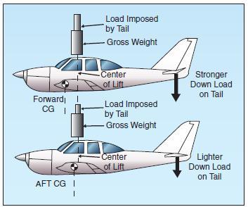
[Figure 3-39. Load distribution affects balance]
Figure 3-39 illustrates the reason for this. With forward loading, “nose-up” trim is required in most airplanes to maintain level cruising flight. Nose-up trim involves setting the tail surfaces to produce a greater down load on the aft portion of the fuselage, which adds to the wing loading and the total lift required from the wing if altitude is to be maintained. This requires a higher angle of attack of the wing, which results in more drag and, in turn, produces a higher stalling speed.
With aft loading and “nose-down” trim, the tail surfaces will exert less down load, relieving the wing of that much wing loading and lift required to maintain altitude. The required angle of attack of the wing is less, so the drag is less, allowing for a faster cruise speed. Theoretically, a neutral load on the tail surfaces in cruising flight would produce the most efficient overall performance and fastest cruising speed, but would also result in instability. Consequently, modern airplanes are designed to require a down load on the tail for stability and controllability.
Remember that a zero indication on the trim tab control is not necessarily the same as “neutral trim” because of the force exerted by downwash from the wings and the fuselage on the tail surfaces.
The effects of the distribution of the airplane’s useful load have a significant influence on its flight characteristics, even when the load is within the center- of-gravity limits and the maximum permissible gross weight. Important among these effects are changes in controllability, stability, and the actual load imposed on the wing.
Generally, an airplane becomes less controllable, especially at slow flight speeds, as the center of gravity is moved further aft. An airplane which cleanly recovers from a prolonged spin with the center of gravity at one position may fail completely to respond to normal recovery attempts when the center of gravity is moved aft by 1 or 2 inches.
It is common practice for airplane designers to establish an aft center-of-gravity limit that is within 1 inch of the maximum which will allow normal recovery from a one-turn spin. When certificating an airplane in the utility category to permit intentional spins, the aft center-of-gravity limit is usually established at a point several inches forward of that which is permissible for certification in the normal category.
Another factor affecting controllability, which is becoming more important in current designs of large airplanes, is the effect of long moment arms to the positions of heavy equipment and cargo. The same airplane may be loaded to maximum gross weight within its center-of-gravity limits by concentrating fuel, passengers, and cargo near the design center of gravity; or by dispersing fuel and cargo loads in wingtip tanks and cargo bins forward and aft of the cabin.
With the same total weight and center of gravity, maneuvering the airplane or maintaining level flight in turbulent air will require the application of greater control forces when the load is dispersed. This is true because of the longer moment arms to the positions of the heavy fuel and cargo loads which must be overcome by the action of the control surfaces. An airplane with full outboard wing tanks or tip tanks tends to be sluggish in roll when control situations are marginal, while one with full nose and aft cargo bins tends to be less responsive to the elevator controls.
The rearward center-of-gravity limit of an airplane is determined largely by considerations of stability. The original airworthiness requirements for a type certificate specify that an airplane in flight at a certain speed will dampen out vertical displacement of the nose within a certain number of oscillations. An airplane loaded too far rearward may not do this; instead when the nose is momentarily pulled up, it may alternately climb and dive becoming steeper with each oscillation. This instability is not only uncomfortable to occupants, but it could even become dangerous by making the airplane unmanageable under certain conditions.
The recovery from a stall in any airplane becomes progressively more difficult as its center of gravity moves aft. This is particularly important in spin recovery, as there is a point in rearward loading of any airplane at which a “flat” spin will develop. A flat spin is one in which centrifugal force, acting through a center of gravity located well to the rear, will pull the tail of the airplane out away from the axis of the spin, making it impossible to get the nose down and recover.
An airplane loaded to the rear limit of its permissible center-of-gravity range will handle differently in turns and stall maneuvers and have different landing characteristics than when it is loaded near the forward limit.
The forward center-of-gravity limit is determined by a number of considerations. As a safety measure, it is required that the trimming device, whether tab or adjustable stabilizer, be capable of holding the airplane in a normal glide with the power off. A conventional airplane must be capable of a full stall, power-off landing in order to ensure minimum landing speed in emergencies. A tailwheel-type airplane loaded excessively nose heavy will be difficult to taxi, particularly in high winds. It can be nosed over easily by use of the brakes, and it will be difficult to land without bouncing since it tends to pitch down on the wheels as it is slowed down and flared for landing. Steering difficulties on the ground may occur in nosewheel-type airplanes, particularly during the landing roll and takeoff.
• The CG position influences the lift and angle of attack of the wing, the amount and direction of force on the tail, and the degree of deflection of the stabilizer needed to supply the proper tail force for equilibrium. The latter is very important because of its relationship to elevator control force.
• The airplane will stall at a higher speed with a forward CG location. This is because the stalling angle of attack is reached at a higher speed due to increased wing loading.
• Higher elevator control forces normally exist with a forward CG location due to the increased stabilizer deflection required to balance the airplane.
• The airplane will cruise faster with an aft CG location because of reduced drag. The drag is reduced because a smaller angle of attack and less downward deflection of the stabilizer are required to support the airplane and overcome the nose-down pitching tendency.
• The airplane becomes less stable as the CG is moved rearward. This is because when the CG is moved rearward it causes an increase in the angle of attack. Therefore, the wing contribution to the airplane’s stability is now decreased, while the tail contribution is still stabilizing. When the point is reached that the wing and tail contributions balance, then neutral stability exists. Any CG movement further aft will result in an unstable airplane.
• Aforward CG location increases the need for greater back elevator pressure. The elevator may no longer be able to oppose any increase in nose-down pitching. Adequate elevator control is needed to control the airplane throughout the airspeed range down to the stall.
HIGH-SPEED FLIGHT
SUPERSONIC VS. SUBSONIC FLOW
In subsonic aerodynamics, the theory of lift is based upon the forces generated on a body and a moving gas (air) in which it is immersed. At speeds below about 260 knots, air can be considered incompressible, in that at a fixed altitude, its density remains nearly constant while its pressure varies. Under this assumption, air acts the same as water and is classified as a fluid. Subsonic aerodynamic theory also assumes the effects of viscosity (the property of a fluid that tends to prevent motion of one part of the fluid with respect to another) are negligible, and classifies air as an ideal fluid, conforming to the principles of ideal-fluid aerodynamics such as continuity, Bernoulli’s principle, and circulation.
In reality, air is compressible and viscous. While the effects of these properties are negligible at low speeds, compressibility effects in particular become increasingly important as speed increases. Compressibility (and to a lesser extent viscosity) is of paramount importance at speeds approaching the speed of sound. In these speed ranges, compressibility causes a change in the density of the air around an airplane.
During flight, a wing produces lift by accelerating the airflow over the upper surface. This accelerated air can, and does, reach sonic speeds even though the airplane itself may be flying subsonic. At some extreme angles of attack, in some airplanes, the speed of the air over the top surface of the wing may be double the airplane’s speed. It is therefore entirely possible to have both supersonic and subsonic airflow on an airplane at the same time. When flow velocities reach sonic speeds at some location on an airplane (such as the area of maximum camber on the wing), further acceleration will result in the onset of compressibility effects such as shock wave formation, drag increase, buffeting, stability, and control difficulties. Subsonic flow principles are invalid at all speeds above this point.
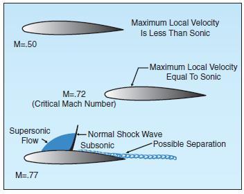
[Figure 3-40. Wing airflow.]
SPEED RANGES
The speed of sound varies with temperature. Under standard temperature conditions of 15°C, the speed of sound at sea level is 661 knots. At 40,000 feet, where the temperature is –55°C, the speed of sound decreases to 574 knots. In high-speed flight and/or high-altitude flight, the measurement of speed is expressed in terms of a “Mach number”—the ratio of the true airspeed of the airplane to the speed of sound in the same atmospheric conditions. An airplane traveling at the speed of sound is traveling at Mach 1.0. Airplane speed regimes are defined as follows:
Subsonic—Mach numbers below 0.75
Transonic—Mach numbers from .075 to 1.20
Supersonic—Mach numbers from 1.20 to 5.00
Hypersonic—Mach numbers above 5.00
While flights in the transonic and supersonic ranges are common occurrences for military airplanes, civilian jet airplanes normally operate in a cruise speed range of Mach 0.78 to Mach 0.90.
The speed of an airplane in which airflow over any part of the wing first reaches (but does not exceed) Mach 1.0 is termed that airplane’s critical Mach number or “Mach Crit.” Thus, critical Mach number is the boundary between subsonic and transonic flight and is an important point of reference for all compressibility effects encountered in transonic flight. Shock waves, buffet, and airflow separation take place above critical Mach number. Ajet airplane typically is most efficient when cruising at or near its critical Mach number. At speeds 5 – 10 percent above the critical Mach number, compressibility effects begin. Drag begins to rise sharply. Associated with the “drag rise” are buffet, trim and stability changes, and a decrease in control surface effectiveness. This is the point of “drag divergence,” and is typically the speed chosen for high-speed cruise operations. At some point beyond high-speed cruise are the turbine powered airplane’s maximum operating limit speeds: VMO/MMO.
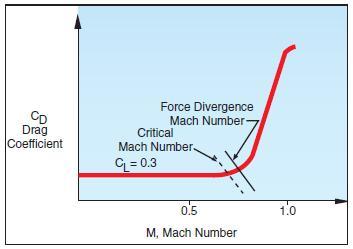
[Figure 3-41. Critical Mach.]
VMO is the maximum operating speed expressed in terms of knots. VMO limits ram air pressure acting against the structure and prevents flutter. MMO is the maximum operating speed expressed in terms of Mach number. An airplane should not be flown in excess of this speed. Doing so risks encountering the full effects of compressibility, including possible loss of control.
MACH NUMBER VS. AIRSPEED
Speeds such as Mach Crit and MMO for a specific airplane occur at a given Mach number. The true airspeed (TAS), however, varies with outside air temperature. Therefore, true airspeeds corresponding to a specific Mach number can vary considerably (as much as 75 – 100 knots). When an airplane cruising at a constant Mach number enters an area of higher outside air temperatures, true airspeed and required fuel increases, and range decreases. Conversely, when entering an area of colder outside air temperatures, true airspeed and fuel flow decreases, and range increases.
In a jet airplane operating at high altitude, the indicated airspeed (IAS) for any given Mach number decreases with an increase in altitude above a certain level. The reverse occurs during descent. Normally, climbs and descents are accomplished using indicated airspeed in the lower altitudes and Mach number in the higher altitudes.
Unlike operations in the lower altitudes, the indicated airspeed (IAS) at which a jet airplane stalls increases significantly with altitude. This is due to the fact that true airspeed (TAS) increases with altitude. At high true airspeeds, air compression causes airflow distortion over the wings and in the pitot system. At the same time, the indicated airspeed (IAS) representing MMO decreases with altitude. Eventually, the airplane can reach an altitude where there is little or no difference between the two.
BOUNDARY LAYER
Air has viscosity, and will encounter resistance to flow over a surface. The viscous nature of airflow reduces the local velocities on a surface and is responsible for skin friction drag. As the air passes over the wing’s surface, the air particles nearest the surface come to rest. The next layer of particles is slowed down but not stopped. Some small but measurable distance from the surface, the air particles are moving at free stream velocity. The layer of air over the wing’s surface, which is slowed down or stopped by viscosity, is termed the “boundary layer.” Typical boundary layer thicknesses on an airplane range from small fractions of an inch near the leading edge of a wing to the order of 12 inches at the aft end of a large airplane such as a Boeing 747.
There are two different types of boundary layer flow: laminar and turbulent. The laminar boundary layer is a very smooth flow, while the turbulent boundary layer contains swirls or “eddies.” The laminar flow creates less skin friction drag than the turbulent flow, but is less stable. Boundary layer flow over a wing surface begins as a smooth laminar flow. As the flow continues back from the leading edge, the laminar boundary layer increases in thickness. At some distance back from the leading edge, the smooth laminar flow breaks down and transitions to a turbulent flow. From a drag standpoint, it is advisable to have the transition from laminar to turbulent flow as far aft on the wing as possible, or have a large amount of the wing surface within the laminar portion of the boundary layer. The low energy laminar flow, however, tends to break down more suddenly than the turbulent layer.
Another phenomenon associated with viscous flow is separation. Separation occurs when the airflow breaks away from an airfoil. The natural progression is from laminar boundary layer to turbulent boundary layer and then to airflow separation. Airflow separation produces high drag and ultimately destroys lift. The boundary layer separation point moves forward on the wing as the angle of attack is increased.
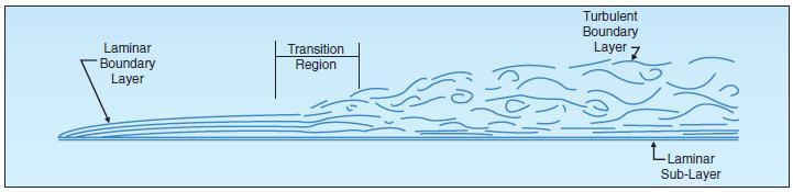
[Figure 3-42 Airflow Boundary layer.]
“Vortex Generators” are used to delay or prevent shock wave induced boundary layer separation encountered in transonic flight. Vortex generators are small low aspect ratio airfoils placed at a 12° to 15° angle of attack to the airstream. They are usually spaced a few inches apart along the wing ahead of the ailerons or other control surfaces. Vortex generators create a vortex which mixes the boundary airflow with the high energy airflow just above the surface. This produces higher surface velocities and increases the energy of the boundary layer. Thus, a stronger shock wave will be necessary to produce airflow separation.
SHOCK WAVES
When an airplane flies at subsonic speeds, the air ahead is “warned” of the airplane’s coming by a pressure change transmitted ahead of the airplane at the speed of sound. Because of this warning, the air begins to move aside before the airplane arrives and is prepared to let it pass easily. When the airplane’s speed reaches the speed of sound, the pressure change can no longer warn the air ahead because the airplane is keeping up with its own pressure waves. Rather, the air particles pile up in front of the airplane causing a sharp decrease in the flow velocity directly in front of the airplane with a corresponding increase in air pressure and density.
As the airplane’s speed increases beyond the speed of sound, the pressure and density of the compressed air ahead of it increase, the area of compression extending some distance ahead of the airplane. At some point in the airstream, the air particles are completely undisturbed, having had no advanced warning of the airplane’s approach, and in the next instant the same air particles are forced to undergo sudden and drastic changes in temperature, pressure, density, and velocity. The boundary between the undisturbed air and the region of compressed air is called a shock or “compression” wave.
This same type of wave is formed whenever a supersonic airstream is slowed to subsonic without a change in direction, such as when the airstream is accelerated to sonic speed over the cambered portion of a wing, and then decelerates to subsonic speed as the area of maximum camber is passed. A shock wave will form as a boundary between the supersonic and subsonic ranges.
Whenever a shock wave forms perpendicular to the airflow, it is termed a “normal” shock wave, and the flow immediately behind the wave is subsonic. A supersonic airstream passing through a normal shock wave will experience these changes:
• The airstream is slowed to subsonic.
• The airflow immediately behind the shock wave does not change direction.
• The static pressure and density of the airstream behind the wave is greatly increased.
• The energy of the airstream (indicated by total pressure—dynamic plus static) is greatly reduced.
Shock wave formation causes an increase in drag. One of the principal effects of a shock wave is the formation of a dense high pressure region immediately behind the wave. The instability of the high pressure region, and the fact that part of the velocity energy of the airstream is converted to heat as it flows through the wave is a contributing factor in the drag increase, but the drag resulting from airflow separation is much greater. If the shock wave is strong, the boundary layer may not have sufficient kinetic energy to withstand airflow separation. The drag incurred in the transonic region due to shock wave formation and airflow separation is known as “wave drag.” When speed exceeds the critical Mach number by about 10 percent, wave drag increases sharply. A considerable increase in thrust (power) is required to increase flight speed beyond this point into the supersonic range where, depending on the airfoil shape and the angle of attack, the boundary layer may reattach.
Normal shock waves form on the wing’s upper surface first. Further increases in Mach number, however, can enlarge the supersonic area on the upper surface and form an additional area of supersonic flow and a normal shock wave on the lower surface. As flight speed approaches the speed of sound, the areas of supersonic flow enlarge and the shock waves move nearer the trailing edge.
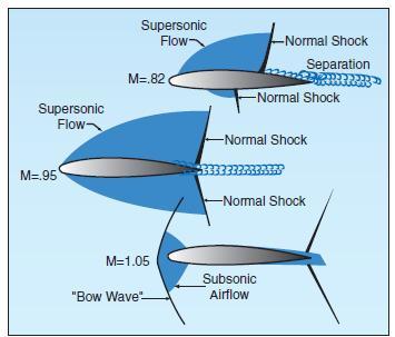
[Figure 3-43. Shock waves]
Associated with “drag rise” are buffet (known as Mach buffet), trim and stability changes, and a decrease in control force effectiveness. The loss of lift due to airflow separation results in a loss of downwash, and a change in the position of the center pressure on the wing. Airflow separation produces a turbulent wake behind the wing which causes the tail surfaces to buffet (vibrate). The nose-up and nose-down pitch control provided by the horizontal tail is dependent on the downwash behind the wing. Thus, a decrease in downwash decreases the horizontal tail’s pitch control effectiveness. Movement of the wing center of pressure affects the wing pitching moment. If the center of pressure moves aft, a diving moment referred to as “Mach tuck” or “tuck under” is produced, and if it moves forward, a nose-up moment is produced. This is the primary reason for the development of the T-tail configuration on many turbine-powered airplanes, which places the horizontal stabilizer as far as practical from the turbulence of the wings.
SWEEPBACK
Most of the difficulties of transonic flight are associated with shock wave induced flow separation. Therefore, any means of delaying or alleviating the shock induced separation will improve aerodynamic performance. One method is wing sweepback. Sweepback theory is based upon the concept that it is only the component of the airflow perpendicular to the leading edge of the wing that affects pressure distribution and formation of shock waves.
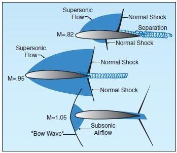
[Figure 3-44 Sweepback effect]
On a straight wing airplane, the airflow strikes the wing leading edge at 90°, and its full impact produces pressure and lift. A wing with sweepback is struck by the same airflow at an angle smaller than 90°. This airflow on the swept wing has the effect of persuading the wing into believing that it is flying slower than it really is; thus the formation of shock waves is delayed. Advantages of wing sweep include an increase in critical Mach number, force divergence Mach number, and the Mach number at which drag rise will peak. In other words, sweep will delay the onset of compressibility effects.
The Mach number, which produces a sharp change in drag coefficient, is termed the “force divergence” Mach number and, for most airfoils, usually exceeds the critical Mach number by 5 to 10 percent. At this speed, the airflow separation induced by shock wave formation can create significant variations in the drag, lift, or pitching moment coefficients. In addition to the delay of the onset of compressibility effects, sweepback reduces the magnitude in the changes of drag, lift or moment coefficients. In other words, the use of sweepback will “soften” the force divergence.
A disadvantage of swept wings is that they tend to stall at the wingtips rather than at the wing roots.
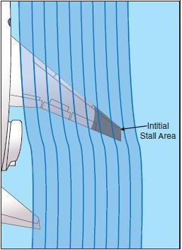
[Figure 3-45 Wingtip stall]
This is because the boundary layer tends to flow spanwise toward the tips and to separate near the leading edges. Because the tips of a swept wing are on the aft part of the wing (behind the center of lift), a wingtip stall will cause the center of lift to move forward on the wing, forcing the nose to rise further. The tendency for tip stall is greatest when wing sweep and taper are combined. Figure 3-45 Wingtip stall. The stall situation can be aggravated by a T-tail configuration, which affords little or no pre-stall warning in the form of tail control surface buffet.
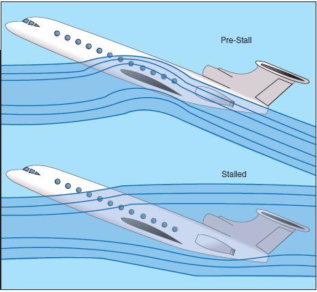
[Figure 3-46.T-tail stall]
The T-tail, being above the wing wake remains effective even after the wing has begun to stall, allowing the pilot to inadvertently drive the wing into a deeper stall at a much greater angle of attack. If the horizontal tail surfaces then become buried in the wing’s wake, the elevator may lose all effectiveness, making it impossible to reduce pitch attitude and break the stall. In the pre-stall and immediate post-stall regimes, the lift/drag qualities of a swept wing airplane (specifically the enormous increase in drag at low speeds) can cause an increasingly descending flightpath with no change in pitch attitude, further increasing the angle of attack. In this situation, without reliable angle of attack information, a nose-down pitch attitude with an increasing airspeed is no guarantee that recovery has been effected, and up-elevator movement at this stage may merely keep the airplane stalled. It is a characteristic of T-tail airplanes to pitch up viciously when stalled in extreme nose-high attitudes, making recovery difficult or violent. The stick pusher inhibits this type of stall. At approximately one knot above stall speed, pre-programmed stick forces automatically move the stick forward, preventing the stall from developing. A “g” limiter may also be incorporated into the system to prevent the pitch down generated by the stick pusher from imposing excessive loads on the airplane. A “stick shaker,” on the other hand provides stall warning when the airspeed is 5 to 7 percent above stall speed.
MACH BUFFET BOUNDARIES
Thus far, only the Mach buffet that results from excessive speed has been addressed. It must be remembered that Mach buffet is a function of the speed of the airflow over the wing—not necessarily the speed of the airplane. Any time that too great a lift demand is made on the wing, whether from too fast an airspeed or from too high an angle of attack near the MMO, the “high-speed” buffet will occur. However, there are also occasions when the buffet can be experienced at much lower speeds known as the “low-speed Mach buffet.”
The most likely situation that could cause the lowspeed buffet would be when the airplane is flown at too slow a speed for its weight and altitude necessitating a high angle of attack. This very high angle of attack would have the effect of increasing airflow velocity over the upper surface of the wing to the point that all of the same effects of the shock waves and buffet would occur as in the high-speed buffet situation. The angle of attack of the wing has the greatest effect on inducing the Mach buffet at either the high-speed or low-speed boundaries for the airplane. The conditions that increase the angle of attack, hence the speed of the airflow over the wing and chances of Mach buffet are as follows:
• High Altitudes—The higher an airplane flies, the thinner the air and the greater the angle of attack required to produce the lift needed to maintain level flight.
• Heavy Weights—The heavier the airplane, the greater the lift required of the wing, and all other things being equal, the greater the angle of attack.
• “G” Loading—An increase in the “G” loading on the airplane has the same effect as increasing the weight of the airplane. Whether the increase in “G” forces is caused by turns, rough control usage, or turbulence, the effect of increasing the wing’s angle of attack is the same.
FLIGHT CONTROLS
On high-speed airplanes, flight controls are divided into primary flight controls and secondary or auxiliary flight controls. The primary flight controls maneuver the airplane about the pitch, roll, and yaw axes. They include the ailerons, elevator, and rudder. Secondary or auxiliary flight controls include tabs, leading edge flaps, trailing edge flaps, spoilers, and slats.
Spoilers are used on the upper surface of the wing to spoil or reduce lift. High-speed airplanes, due to their clean low drag design use spoilers as speed brakes to slow them down. Spoilers are extended immediately after touchdown to dump lift and thus transfer the weight of the airplane from the wings onto the wheels for better braking performance.
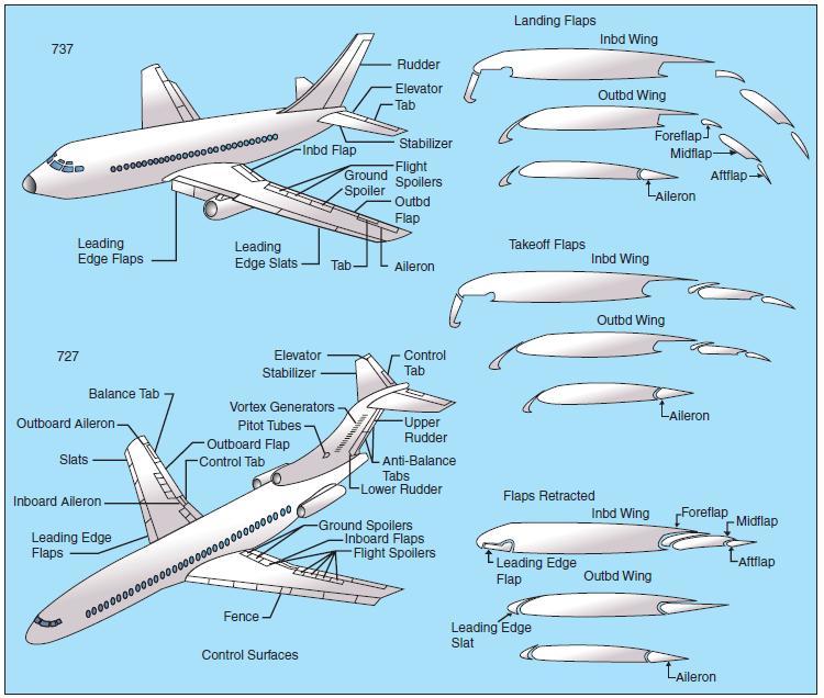
[Figure 3-47 flight control surfaces]
Jet transport airplanes have small ailerons. The space for ailerons is limited because as much of the wing trailing edge as possible is needed for flaps. Another reason is that a conventional size aileron would cause wing twist at high speed. Because the ailerons are necessarily small, spoilers are used in unison with ailerons to provide additional roll control.
Some jet transports have two sets of ailerons; a pair of outboard low-speed ailerons, and a pair of high-speed inboard ailerons. When the flaps are fully retracted after takeoff, the outboard ailerons are automatically locked out in the faired position.
When used for roll control, the spoiler on the side of the up-going aileron extends and reduces the lift on that side, causing the wing to drop. If the spoilers are extended as speed brakes, they can still be used for roll control. If they are the Differential type, they will extend further on one side and retract on the other side. If they are the Non-Differential type, they will extend further on one side but will not retract on the other side. When fully extended as speed brakes, the Non- Differential spoilers remain extended and do not supplement the ailerons.
To obtain a smooth stall and a higher angle of attack without airflow separation, an airplane’s wing leading edge should have a well-rounded almost blunt shape that the airflow can adhere to at the higher angle of attack. With this shape, the airflow separation will start at the trailing edge and progress forward gradually as angle of attack is increased.
The pointed leading edge necessary for high-speed flight results in an abrupt stall and restricts the use of trailing edge flaps because the airflow cannot follow the sharp curve around the wing leading edge. The airflow tends to tear loose rather suddenly from the upper surface at a moderate angle of attack. To utilize trailing edge flaps, and thus increase the maximum lift coefficient, the wing must go to a higher angle of attack without airflow separation. Therefore, leading edge slots, slats, and flaps are used to improve the low-speed characteristics during takeoff, climb, and landing. Although these devices are not as powerful as trailing edge flaps, they are effective when used full span in combination with high-lift trailing edge flaps. With the aid of these sophisticated high-lift devices, airflow separation is delayed and the maximum lift coefficient (CLmax) is increased considerably. In fact, a 50-knot reduction in stall speed is not uncommon.
The operational requirements of a large jet transport airplane necessitate large pitch trim changes. Some of these requirements are:
• The requirement for a large CG range.
• The need to cover a large speed range.
• The need to cope with possibly large trim changes due to wing leading edge and trailing edge high-lift devices without limiting the amount of elevator remaining.
• The need to reduce trim drag to a minimum.
These requirements are met by the use of a variable incidence horizontal stabilizer. Large trim changes on a fixed-tail airplane require large elevator deflections. At these large deflections, little further elevator movement remains in the same direction. A variable incidence horizontal stabilizer is designed to take out the trim changes. The stabilizer is larger than the elevator, and consequently does not need to be moved through as large an angle. This leaves the elevator streamlining the tail plane with a full range of movement up and down. The variable incidence horizontal stabilizer can be set to handle the bulk of the pitch control demand, with the elevator handling the rest. On airplanes equipped with a variable incidence horizontal stabilizer, the elevator is smaller and less effective in isolation than it is on a fixed-tail airplane. In comparison to other flight controls, the variable incidence horizontal stabilizer is enormously powerful in its effect. Its use and effect must be fully understood and appreciated by flight crewmembers.
Because of the size and high speeds of jet transport airplanes, the forces required to move the control surfaces can be beyond the strength of the pilot. Consequently, the control surfaces are actuated by hydraulic or electrical power units. Moving the controls in the cockpit signals the control angle required, and the power unit positions the actual control surface. In the event of complete power unit failure, movement of the control surface can be effected by manually controlling the control tabs. Moving the control tab upsets the aerodynamic balance which causes the control surface to move.
Selected Knowledge field from the left to find out more about knowledge related to Pilot Training.
Click here to get a complete list of Aircraft Schools the entire United States.
Copyright © 2012 AirplaneGroundSchools.com | All Rights Reserved
Design G. Wolfgang | W3C XHTML 1.0 | W3C CSS 2.0
Courtesy Open Web Design![]() Thanks to Florida Vacation Homes
Thanks to Florida Vacation Homes