Airplane Ground Schools
Knowledge of Flying is Our passion.
Serving the General Aviation Community
PITOT-STATIC FLIGHT INSTRUMENTS
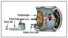
There are two major parts of the pitot-static system: the impact pressure chamber and lines, and the static pressure chamber and lines. They provide the source of ambient air pressure for the operation of the altimeter, vertical speed indicator (vertical velocity indicator), and the airspeed indicator.
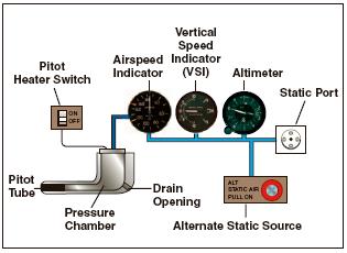
[Figure 6-1 Pitot-static system and instruments]
IMPACT PRESSURE CHAMBER AND LINES
In this system, the impact air pressure (air striking the airplane because of its forward motion) is taken from a pitot tube, which is mounted in locations that provide minimum disturbance or turbulence caused by the motion of the airplane through the air. The static pressure (pressure of the still air) is usually taken from the static line attached to a vent or vents mounted flush with the side of the fuselage. This compensates for any possible variation in static pressure due to erratic changes in airplane attitude.
The openings of both the pitot tube and the static vent must be checked during the preflight inspection to assure that they are free from obstructions. Blocked or partially blocked openings should be cleaned by a certificated mechanic. Blowing into these openings is not recommended because this could damage the instruments.
As the airplane moves through the air, the impact pressure on the open pitot tube affects the pressure in the pitot chamber. Any change of pressure in the pitot chamber is transmitted through a line connected to the airspeed indicator, which utilizes impact pressure for its operation.
STATIC PRESSURE CHAMBER AND LINES
The static chamber is vented through small holes to the free undisturbed air, and as the atmospheric pressure increases or decreases, the pressure in the static chamber changes accordingly. Again, this pressure change is transmitted through lines to the instruments which utilize static pressure.
An alternate source for static pressure is provided in some airplanes in the event the static ports become blocked. This source usually is vented to the pressure inside the cockpit. Because of the venturi effect of the flow of air over the cockpit, this alternate static pressure is usually lower than the pressure provided by the normal static air source. When the alternate static source is used, the following differences in the instrument indications usually occur: the altimeter will indicate higher than the actual altitude, the airspeed will indicate greater than the actual airspeed, and the vertical speed will indicate a climb while in level flight. Consult the Airplane Flight Manual or Pilot’s Operating Handbook (AFM/POH) to determine the amount of error.
If the airplane is not equipped with an alternate static source, breaking the glass seal of the vertical speed indicator allows ambient air pressure to enter the static system. This makes the VSI unusable.
ALTIMETER
The altimeter measures the height of the airplane above a given pressure level. Since it is the only instrument that gives altitude information, the altimeter is one of the most vital instruments in the airplane. To use the altimeter effectively, its operation and how atmospheric pressure and temperature affect it must be thoroughly understood. A stack of sealed aneroid wafers comprises the main component of the altimeter. These wafers expand and contract with changes in atmospheric pressure from the static source. The mechanical linkage translates these changes into pointer movements on the indicator.
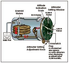
[Figure 6-2 Altimeter]
PRINCIPLE OF OPERATION
The pressure altimeter is an aneroid barometer that measures the pressure of the atmosphere at the level where the altimeter is located, and presents an altitude indication in feet. The altimeter uses static pressure as its source of operation. Air is denser at sea level than aloft, so as altitude increases, atmospheric pressure decreases. This difference in pressure at various levels causes the altimeter to indicate changes in altitude.
The presentation of altitude varies considerably between different types of altimeters. Some have one pointer while others have two or more. Only the multipointer type will be discussed in this handbook. The dial of a typical altimeter is graduated with numerals arranged clockwise from 0 to 9. Movement of the aneroid element is transmitted through gears to the three hands that indicate altitude. The shortest hand indicates altitude in tens of thousands of feet; the intermediate hand in thousands of feet; and the longest hand in hundreds of feet.
This indicated altitude is correct, however, only when the sea level barometric pressure is standard (29.92 inches of mercury), the sea level free air temperature is standard (+15°C or 59°F), and the pressure and temperature decrease at a standard rate with an increase in altitude. Adjustments for nonstandard conditions are accomplished by setting the corrected pressure into a barometric scale located on the face of the altimeter. Only after the altimeter is set does it indicate the correct altitude.
EFFECT OF NONSTANDARD PRESSURE AND TEMPERATURE
If no means were provided for adjusting altimeters to nonstandard pressure, flight could be hazardous. For example, if flying from a high-pressure area to a low-pressure area without adjusting the altimeter, the actual altitude of the airplane would be LOWER than the indicated altitude. An old saying, “HIGH TO LOW, LOOK OUT BELOW” is a way of remembering which condition is dangerous. When flying from a low-pressure area to a high-pressure area without adjusting the altimeter, the actual altitude of the airplane is HIGHER than the indicated altitude.
Figure 6-3 shows how variations in air temperature also affect the altimeter. On a warm day, a given mass of air expands to a larger volume than on a cold day, raising the pressure levels. For example, the pressure level where the altimeter indicates 5,000 feet is HIGHER on a warm day than under standard conditions. On a cold day, the reverse is true, and the pressure level where the altimeter indicates 5,000 feet is LOWER.
The adjustment to compensate for nonstandard pressure does not compensate for nonstandard temperature.
Aneroid—A sealed flexible container, which expands or contracts in relation to the surrounding air pressure. It is used in an altimeter or a barometer to measure the pressure of the air.
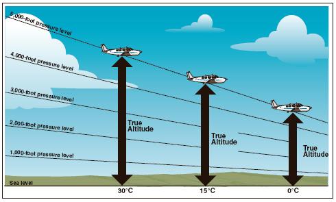
[Figure 6-3. Effects of nonstandard temperature on an altimeter]
If terrain or obstacle clearance is a factor in selecting a cruising altitude, particularly at higher altitudes, remember to anticipate that a colder-than-standard temperature places the airplane LOWER than the altimeter indicates. Therefore, it is necessary to use a higher indicated altitude to provide adequate terrain clearance. Modify the memory aid to “HIGH TO LOW OR HOT TO COLD, LOOK OUT BELOW.”
SETTING THE ALTIMETER
Most altimeters are equipped with a barometric pressure setting window (sometimes referred to as the Kollsman window) providing a means to adjust the altimeter. A knob is located at the bottom of the instrument for this adjustment.
To adjust the altimeter for variation in atmospheric pressure, the pressure scale in the altimeter setting window, calibrated in inches of mercury (in. Hg) and/or millibars (Mb), is adjusted to match the given altimeter setting. Altimeter setting is defined as station pressure reduced to sea level. However, an altimeter setting is accurate only in the vicinity of the reporting station. Therefore, the altimeter must be adjusted as the flight progresses from one station to the next.
Many pilots confidently expect that the current altimeter setting will compensate for irregularities in atmospheric pressure at all altitudes, but this is not always true. The altimeter setting broadcast by ground stations is the station pressure corrected to mean sea level. It does not account for the irregularities at higher levels, particularly the effect of nonstandard temperature. However, if each pilot in a given area is using the same altimeter setting, each altimeter should be equally affected by temperature and pressure variation errors, making it possible to maintain the desired vertical separation between aircraft.
When flying over high, mountainous terrain, certain atmospheric conditions can cause the altimeter to indicate an altitude of 1,000 feet, or more, HIGHER than the actual altitude. For this reason, a generous margin of altitude should be allowed—not only for possible altimeter error, but also for possible downdrafts that might be associated with high winds.
To illustrate the use of the altimeter setting system, follow a flight from Dallas Love Field, Texas to Abilene Municipal Airport, Texas via Mineral Wells. Before taking off from Love Field, the pilot receives a current altimeter setting of 29.85 from the control tower or automatic terminal information service (ATIS), and sets this value in the altimeter setting window.
Automatic Terminal Information Service (ATIS)—The continuous broadcast of recorded noncontrol information in selected terminal areas. Its purpose is to improve controller effectiveness and to relieve frequency congestion by automating the repetitive transmission of essential but routine information.
The altimeter indication should then be compared with the known airport elevation of 487 feet. Since most altimeters are not perfectly calibrated, an error may exist.
When over Mineral Wells, assume the pilot receives a current altimeter setting of 29.94 and sets this in the altimeter window. Before entering the traffic pattern at Abilene Municipal Airport, a new altimeter setting of 29.69 is received from the Abilene Control Tower, and set in the altimeter setting window. If the pilot desires to fly the traffic pattern at approximately 800 feet above the terrain, and the field elevation of Abilene is 1,791 feet, an indicated altitude of 2,600 feet should be maintained (1,791 feet + 800 feet = 2,591 feet rounded to 2,600 feet).
The importance of properly setting the altimeter cannot be overemphasized. Assume that the pilot did not adjust the altimeter at Abilene to the current setting, and continued using the Mineral Wells setting of 29.94. When entering the Abilene traffic pattern at an indicated altitude of 2,600 feet, the airplane would be approximately 250 feet below the proper traffic pattern altitude. Upon landing, the altimeter would indicate approximately 250 feet higher than the field elevation
Altimeter setting 29.94
Current altimeter setting 29.69
Difference .25
(Since 1 inch of pressure is equal to approximately 1,000 feet of altitude, .25 x 1,000 feet = 250 feet.)
When determining whether to add or subtract the amount of altimeter error, remember that, when the actual pressure is lower than what is set in the altimeter window, the actual altitude of the airplane will be lower than what is indicated on the altimeter.
ALTIMETER OPERATION
There are two means by which the altimeter pointers can be moved. The first is a change in air pressure, while the other is an adjustment to the barometric scale. When the airplane climbs or descends, changing pressure within the altimeter case expands or contracts the aneroid barometer. This movement is transmitted through mechanical linkage to rotate the pointers. A decrease in pressure causes the altimeter to indicate an increase in altitude, and an increase in pressure causes the altimeter to indicate a decrease in altitude. Accordingly, if the airplane is flown from a pressure level of 28.75 in. Hg. to a pressure level of 29.75 in. Hg., the altimeter would show a decrease of approximately 1,000 feet in altitude.
The other method of moving the pointers does not rely on changing air pressure, but the mechanical construction of the altimeter. Do not be confused by the fact that as the barometric pressure scale is moved, the indicator needles move in the same direction, which is opposite to the reaction the pointers have when air pressure changes. To illustrate this point, suppose the pilot lands at an airport with an elevation of 1,000 feet and the altimeter is correctly set to the current sea level pressure of 30.00 in. Hg. While the airplane is parked on the ramp, the pressure decreases to 29.50. The altimeter senses this as a climb and now indicates 1,500 feet. When returning to the airplane, if the setting in the altimeter window is decreased to the current sea level pressure of 29.50, the indication will be reduced back down to 1,000 feet.
Knowing the airplane’s altitude is vitally important to a pilot. The pilot must be sure that the airplane is flying high enough to clear the highest terrain or obstruction along the intended route. It is especially important to have accurate altitude information when visibility is restricted. To clear obstructions, the pilot must constantly be aware of the altitude of the airplane and the elevation of the surrounding terrain. To reduce the possibility of a midair collision, it is essential to maintain altitude in accordance with air traffic rules.
TYPES OF ALTITUDE
Altitude is vertical distance above some point or level used as a reference. There are as many kinds of altitude as there are reference levels from which altitude is measured, and each may be used for specific reasons. Pilots are mainly concerned with five types of altitudes:
Indicated Altitude—That altitude read directly from the altimeter (uncorrected) when it is set to the current altimeter setting.
True Altitude—The vertical distance of the airplane above sea level—the actual altitude. It is often expressed as feet above mean sea level (MSL). Airport, terrain, and obstacle elevations on aeronautical charts are true altitudes. Absolute Altitude—The vertical distance of an airplane above the terrain, or above ground level (AGL).
Pressure Altitude—The altitude indicated when the altimeter setting window (barometric scale) is adjusted to 29.92. This is the altitude above the standard datum plane, which is a theoretical plane where air pressure(corrected to 15°C) equals 29.92 in. Hg. Pressure altitude is used to compute density altitude, true altitude, true airspeed, and other performance data.
Density Altitude—This altitude is pressure altitude corrected for variations from standard temperature. When conditions are standard, pressure altitude and density altitude are the same. If the temperature is above standard, the density altitude is higher than pressure altitude. If the temperature is below standard, the density altitude is lower than pressure altitude. This is an important altitude because it is directly related to the airplane’s performance.
As an example, consider an airport with a field elevation of 5,048 feet MSL where the standard temperature is 5°C. Under these conditions, pressure altitude and density altitude are the same—5,048 feet. If the temperature changes to 30°C, the density altitude increases to 7,855 feet. This means an airplane would perform on takeoff as though the field elevation were 7,855 feet at standard temperature. Conversely, a temperature of -25°C would result in a density altitude of 1,232 feet. An airplane would have much better performance under these conditions.
Instrument Check—To determine the condition of an altimeter, set the barometric scale to the altimeter setting transmitted by the local automated flight service station (AFSS) or any other reliable source. The altimeter pointers should indicate the surveyed elevation of the airport. If the indication is off more than 75 feet from the surveyed elevation, the instrument should be referred to a certificated instrument repair station for recalibration.
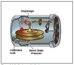
VERTICAL SPEED INDICATOR
The vertical speed indicator (VSI), which is sometimes called a vertical velocity indicator (VVI), indicates whether the airplane is climbing, descending, or in level flight. The rate of climb or descent is indicated in feet per minute. If properly calibrated, the VSI indicates zero in level flight.
[Figure 6-4 Vertical Speed Indicator]
PRINCIPLE OF OPERATION
Although the vertical speed indicator operates solely from static pressure, it is a differential pressure instrument. It contains a diaphragm with connecting linkage and gearing to the indicator pointer inside an airtight case. The inside of the diaphragm is connected directly to the static line of the pitot-static system. The area outside the diaphragm, which is inside the instrument case, is also connected to the static line, but through a restricted orifice (calibrated leak).
Both the diaphragm and the case receive air from the static line at existing atmospheric pressure. When the airplane is on the ground or in level flight, the pressures inside the diaphragm and the instrument case remain the same and the pointer is at the zero indication. When the airplane climbs or descends, the pressure inside the diaphragm changes immediately, but due to the metering action of the restricted passage, the case pressure remains higher or lower for a short time, causing the diaphragm to contract or expand. This causes a pressure differential that is indicated on the instrument needle as a climb or descent. When the pressure differential stabilizes at a definite ratio, the needle indicates the rate of altitude change.
The vertical speed indicator is capable of displaying two different types of information:
• Trend information shows an immediate indication of an increase or decrease in the airplane’s rate of climb or descent.
• Rate information shows a stabilized rate of change in altitude.
For example, if maintaining a steady 500-foot per minute (f.p.m.) climb, and the nose is lowered slightly, the VSI immediately senses this change and indicates a decrease in the rate of climb. This first indication is called the trend. After a short time, the VSI needle stabilizes on the new rate of climb, which in this example, is something less than 500 f.p.m. The time from the initial change in the rate of climb, until the VSI displays an accurate indication of the new rate, is called the lag. Rough control technique and turbulence can extend the lag period and cause erratic and unstable rate indications. Some airplanes are equipped with an instantaneous vertical speed indicator (IVSI), which incorporates accelerometers to compensate for the lag in the typical VSI.
[Figure 6-5]
Instrument Check—To verify proper operation, make sure the VSI is indicating near zero prior to takeoff. After takeoff, it should indicate a positive rate of climb.
AIRSPEED INDICATOR
The airspeed indicator is a sensitive, differential pressure gauge which measures and shows promptly the difference between pitot or impact pressure, and static pressure, the undisturbed atmospheric pressure at level flight. These two pressures will be equal when the airplane is parked on the ground in calm air. When the airplane moves through the air, the pressure on the pitot line becomes greater than the pressure in the static lines. This difference in pressure is registered by the airspeed pointer on the face of the instrument, which is calibrated in miles per hour, knots, or both.
[Figure 6-6 An Instantaneous vertical speed indicator incoperates accelerometers to help the instrument immediately indicate changes in verticle speed.]
Pilots should understand the following speeds:
Indicated Airspeed (IAS)—The direct instrument reading obtained from the airspeed indicator, uncorrected for variations in atmospheric density, installation error, or instrument error. Manufacturers use this airspeed as the basis for determining airplane performance. Takeoff, landing, and stall speeds listed in the AFM or POH are indicated airspeeds and do not normally vary with altitude or temperature.
Calibrated Airspeed (CAS)—Indicated airspeed corrected for installation error and instrument error. Although manufacturers attempt to keep airspeed errors to a minimum, it is not possible to eliminate all errors throughout the airspeed operating range. At certain airspeeds and with certain flap settings, the installation and instrument errors may total several knots. This error is generally greatest at low airspeeds. In the cruising and higher airspeed ranges, indicated airspeed and calibrated airspeed are approximately the same. Refer to the airspeed calibration chart to correct for possible airspeed errors.
True Airspeed (TAS)—Calibrated airspeed corrected for altitude and nonstandard temperature. Because air density decreases with an increase in altitude, an airplane has to be flown faster at higher altitudes to cause the same pressure difference between pitot impact pressure and static pressure. Therefore, for a given calibrated airspeed, true airspeed increases as altitude increases; or for a given true airspeed, calibrated airspeed decreases as altitude increases.
A pilot can find true airspeed by two methods. The most accurate method is to use a flight computer. With this method, the calibrated airspeed is corrected for temperature and pressure variation by using the airspeed correction scale on the computer. Extremely accurate electronic flight computers are also available. Just enter the CAS, pressure altitude, and temperature and the computer calculates the true airspeed.
A second method, which is a “rule of thumb,” will provide the approximate true airspeed. Simply add 2 percent to the calibrated airspeed for each 1,000 feet of altitude.
Groundspeed (GS)—The actual speed of the airplane over the ground. It is true airspeed adjusted for wind. Groundspeed decreases with a headwind, and increases with a tailwind.
AIRSPEED INDICATOR MARKINGS
Airplanes weighing 12,500 pounds or less, manufactured after 1945, and certificated by the FAA, are required to have airspeed indicators marked in
Knots—Nautical miles per hour.
accordance with a standard color-coded marking system. This system of color-coded markings enables a pilot to determine at a glance certain airspeed limitations that are important to the safe operation of the airplane. For example, if during the execution of a maneuver, it is noted that the airspeed needle is in the yellow arc and rapidly approaching the red line, the immediate reaction should be to reduce airspeed.
As shown in figure 6-7, airspeed indicators on singleengine small airplanes include the following standard color-coded markings:
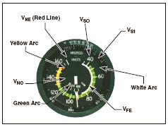
[Figure 6-7. In addition to delineating various speed ranges, the boundaries of the color-coded arcs also identify airspeed limitations.]
• White arc—This arc is commonly referred to as the flap operating range since its lower limit represents the full flap stall speed and its upper limit provides the maximum flap speed. Approaches and landings are usually flown at speeds within the white arc.
• Lower limit of white arc (VS0)—The stalling speed or the minimum steady flight speed in the landing configuration. In small airplanes, this is the power-off stall speed at the maximum landing weight in the landing configuration (gear and flaps down).
• Upper limit of the white arc (VFE)—The maximum speed with the flaps extended. • Green arc—This is the normal operating range of the airplane. Most flying occurs within this range.
• Lower limit of green arc (VS1)—The stalling speed or the minimum steady flight speed obtained in a specified configuration. For most airplanes, this is the power-off stall speed at the maximum takeoff weight in the clean configuration (gear up, if retractable, and flaps up).
• Upper limit of green arc (VNO)—The maximum structural cruising speed. Do not exceed this speed except in smooth air.
• Yellow arc—Caution range. Fly within this range only in smooth air, and then, only with caution.
• Red line (VNE)—Never-exceed speed. Operating above this speed is prohibited since it may result in damage or structural failure.
OTHER AIRSPEED LIMITATIONS
Some important airspeed limitations are not marked on the face of the airspeed indicator, but are found on placards and in the AFM or POH. These airspeeds include:
• Design maneuvering speed (VA)—This is the “rough air” speed and the maximum speed for abrupt maneuvers. If during flight, rough air or severe turbulence is encountered, reduce the airspeed to maneuvering speed or less to minimize stress on the airplane structure. It is important to consider weight when referencing this speed. For example, VA may be 100 knots when an airplane is heavily loaded, but only 90 knots when the load is light.
• Landing gear operating speed (VLO)—The maximum speed for extending or retracting the landing gear if using an airplane equipped with retractable landing gear.
• Landing gear extended speed (VLE)—The maximum speed at which an airplane can be safely flown with the landing gear extended.
• Best angle-of-climb speed (VX)—The airspeed at which an airplane gains the greatest amount of altitude in a given distance. It is used during a short-field takeoff to clear an obstacle.
• Best rate-of-climb speed (VY)—This airspeed provides the most altitude gain in a given period of time.
• Minimum control speed (VMC)—This is the minimum flight speed at which a light, twin-engine airplane can be satisfactorily controlled when an engine suddenly becomes inoperative and the remaining engine is at takeoff power.
• Best rate of climb with one engine inoperative (VYSE)—This airspeed provides the most altitude gain in a given period of time in a light, twinengine airplane following an engine failure.
Instrument Check—Prior to takeoff, the airspeed indicator should read zero. However, if there is a strong wind blowing directly into the pitot tube, the airspeed indicator may read higher than zero. When beginning the takeoff, make sure the airspeed is increasing at an appropriate rate.
BLOCKAGE OF THE PITOT-STATIC SYSTEM
Errors almost always indicate blockage of the pitot tube, the static port(s), or both. Blockage may be caused by moisture (including ice), dirt, or even insects. During preflight, make sure the pitot tube cover is removed. Then, check the pitot and static port openings. A blocked pitot tube affects the accuracy of only the airspeed indicator. However, a blockage of the static system not only affects the airspeed indicator, but can also cause errors in the altimeter and vertical speed indicator.
BLOCKED PITOT SYSTEM
The pitot system can become blocked completely or only partially if the pitot tube drain hole remains open. If the pitot tube becomes blocked and its associated drain hole remains clear, ram air no longer is able to enter the pitot system. Air already in the system will vent through the drain hole, and the remaining pressure will drop to ambient (outside) air pressure. Under these circumstances, the airspeed indicator reading decreases to zero, because the airspeed indicator senses no difference between ram and static air pressure. The airspeed indicator acts as if the airplane were stationary on the ramp. The apparent loss of airspeed is not usually instantaneous. Instead, the airspeed will drop toward zero.
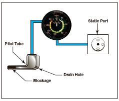
[Figure 6-8 A blocked pitot tube, but clear drain hole]
If the pitot tube, drain hole, and static system all become blocked in flight, changes in airspeed will not be indicated, due to the trapped pressures. However, if the static system remains clear, the airspeed indicator acts as an altimeter. An apparent increase in the ram air pressure relative to static pressure occurs as altitude increases above the level where the pitot tube and drain hole became blocked. This pressure differential causes the airspeed indicator to show an increase in speed. A decrease in indicated airspeed occurs as the airplane descends below the altitude at which the pitot system became blocked.
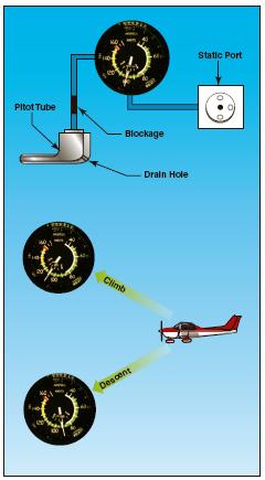
[Figure 6-9 Blocked Pitot System with clear static system]
The pitot tube may become blocked during flight through visible moisture. Some airplanes may be equipped with pitot heat for flight in visible moisture. Consult the AFM or POH for specific procedures regarding the use of pitot heat.
BLOCKED STATIC SYSTEM
If the static system becomes blocked but the pitot tube remains clear, the airspeed indicator continues to operate; however, it is inaccurate. Airspeed indications are slower than the actual speed when the airplane is operated above the altitude where the static ports became blocked, because the trapped static pressure is higher than normal for that altitude. When operating at a lower altitude, a faster than actual airspeed is displayed due to the relatively low static pressure trapped in the system.
A blockage of the static system also affects the altimeter and VSI. Trapped static pressure causes the altimeter to freeze at the altitude where the blockage occurred. In the case of the VSI, a blocked static system produces a continuous zero indication.

[Figure 6-10 Blocked Static System]
(Courtesy FAA)