Airplane Ground Schools
Knowledge of Flying is Our passion.
Serving the General Aviation Community
|
|
INDUCTION SYSTEMS
The induction system brings in air from the outside, mixes it with fuel, and delivers the fuel/air mixture to the cylinder where combustion occurs. Outside air enters the induction system through an intake port on the front of the engine cowling. This port normally contains an air filter that inhibits the entry of dust and other foreign objects. Since the filter may occasionally become clogged, an alternate source of air must be available. Usually, the alternate air comes from inside the engine cowling, where it bypasses a clogged air filter. Some alternate air sources function automatically, while others operate manually.
Two types of induction systems are commonly used in small airplane engines:
1. the carburetor system, which mixes the fuel and air in the carburetor before this mixture enters the intake manifold, and
2. the fuel injection system, which mixes the fuel and air just before entry into each cylinder.
CARBURETOR SYSTEMS
Carburetors are classified as either float-type or pressure-type. Pressure carburetors are usually not found on small airplanes. The basic difference between a pressure carburetor and a float-type is the pressure carburetor delivers fuel under pressure by a fuel pump.
In the operation of the float-type carburetor system, the outside air first flows through an air filter, usually located at an air intake in the front part of the engine cowling. This filtered air flows into the carburetor and through a venturi, a narrow throat in the carburetor. When the air flows through the venturi, a low-pressure area is created, which forces the fuel to flow through a main fuel jet located at the throat. The fuel then flows into the airstream, where it is mixed with the flowing air. See figure 5-7.
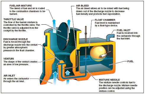
[Figure 5-7. Float-type carburetor.]
The fuel/air mixture is then drawn through the intake manifold and into the combustion chambers, where it is ignited. The “float-type carburetor” acquires its name from a float, which rests on fuel within the float chamber. A needle attached to the float opens and closes an opening at the bottom of the carburetor bowl. This meters the correct amount of fuel into the carburetor, depending upon the position of the float, which is controlled by the level of fuel in the float chamber. When the level of the fuel forces the float to rise, the needle valve closes the fuel opening and shuts off the fuel flow to the carburetor. The needle valve opens again when the engine requires additional fuel. The flow of the fuel/air mixture to the combustion chambers is regulated by the throttle valve, which is controlled by the throttle in the cockpit.
MIXTURE CONTROL
Carburetors are normally calibrated at sea-level pressure, where the correct fuel-to-air mixture ratio is established with the mixture control set in the FULL RICH position. However, as altitude increases, the density of air entering the carburetor decreases, while the density of the fuel remains the same. This creates a progressively richer mixture, which can result in engine roughness and an appreciable loss of power. The roughness normally is due to spark plug fouling from excessive carbon buildup on the plugs. Carbon buildup occurs because the excessively rich mixture lowers the temperature inside the cylinder, inhibiting complete combustion of the fuel. This condition may occur during the pretakeoff runup at high-elevation airports and during climbs or cruise flight at high altitudes. To maintain the correct fuel/air mixture, you must lean the mixture using the mixture control. Leaning the mixture decreases fuel flow, which compensates for the decreased air density at high altitude.
During a descent from high altitude, the opposite is true. The mixture must be enriched, or it may become too lean. An overly lean mixture causes detonation, which may result in rough engine operation, overheating, and a loss of power. The best way to maintain the proper mixture is to monitor the engine temperature and enrichen the mixture as needed. Proper mixture control and better fuel economy for fuel-injected engines can be achieved by use of an exhaust gas temperature gauge. Since the process of adjusting the mixture can vary from one airplane to another, it is important to refer to the Airplane Flight Manual (AFM) or the Pilot’s Operating Handbook (POH) to determine the specific procedures for a given airplane.
CARBURETOR ICING
One disadvantage of the float-type carburetor is its icing tendency. Carburetor ice occurs due to the effect of fuel vaporization and the decrease in air pressure in the venturi, which causes a sharp temperature drop in the carburetor. If water vapor in the air condenses when the carburetor temperature is at or below freezing, ice may form on internal surfaces of the carburetor, including the throttle valve.
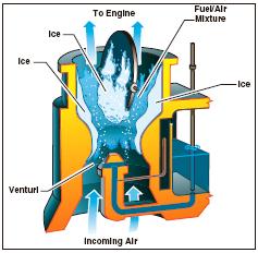
[Figure 5-8. The formation of carburetor ice may reduce or
block fuel/air flow to the engine.]
The reduced air pressure, as well as the vaporization of fuel, contributes to the temperature decrease in the carburetor. Ice generally forms in the vicinity of the throttle valve and in the venturi throat. This restricts the flow of the fuel/air mixture and reduces power. If enough ice builds up, the engine may cease to operate.
Carburetor ice is most likely to occur when temperatures are below 70°F (21°C) and the relative humidity is above 80 percent. However, due to the sudden cooling that takes place in the carburetor, icing can occur even with temperatures as high as 100°F (38°C) and humidity as low as 50 percent. This temperature drop can be as much as 60 to 70°F. Therefore, at an outside air temperature of 100°F, a temperature drop of 70°F results in an air temperature in the carburetor of 30°F.
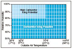
[Figure 5-9. Although carburetor ice is most likely to form when the temperature and humidity are in ranges indicated by this chart, carburetor ice is possible under conditions not depicted.]
The first indication of carburetor icing in an airplane with a fixed-pitch propeller is a decrease in engine r.p.m., which may be followed by engine roughness. In an airplane with a constant-speed propeller, carburetor icing usually is indicated by a decrease in manifold pressure, but no reduction in r.p.m. Propeller pitch is automatically adjusted to compensate for loss of power. Thus, a constant r.p.m. is maintained. Although carburetor ice can occur during any phase of flight, it is particularly dangerous when using reduced power during a descent. Under certain conditions, carburetor ice could build unnoticed until you try to add power. To combat the effects of carburetor ice, engines with float-type carburetors employ a carburetor heat system.
CARBURETOR HEAT
Carburetor heat is an anti-icing system that preheats the air before it reaches the carburetor. Carburetor heat is intended to keep the fuel/air mixture above the freezing temperature to prevent the formation of carburetor ice. Carburetor heat can be used to melt ice that has already formed in the carburetor provided that the accumulation is not too great. The emphasis, however, is on using carburetor heat as a preventative measure.
The carburetor heat should be checked during the engine runup. When using carburetor heat, follow the manufacturer’s recommendations.
When conditions are conducive to carburetor icing during flight, periodic checks should be made to detect its presence. If detected, full carburetor heat should be applied immediately, and it should be left in the ON position until you are certain that all the ice has been removed. If ice is present, applying partial heat or leaving heat on for an insufficient time might aggravate the situation. In extreme cases of carburetor icing, even after the ice has been removed, full carburetor heat should be used to prevent further ice formation. A carburetor temperature gauge, if installed, is very useful in determining when to use carburetor heat.
Whenever the throttle is closed during flight, the engine cools rapidly and vaporization of the fuel is less complete than if the engine is warm. Also, in this condition, the engine is more susceptible to carburetor icing. Therefore, if you suspect carburetor icing conditions and anticipate closed-throttle operation, adjust the carburetor heat to the full ON position before closing the throttle, and leave it on during the closed-throttle operation. The heat will aid in vaporizing the fuel, and help prevent the formation of carburetor ice. Periodically, open the throttle smoothly for a few seconds to keep the engine warm, otherwise the carburetor heater may not provide enough heat to prevent icing.
The use of carburetor heat causes a decrease in engine power, sometimes up to 15 percent, because the heated air is less dense than the outside air that had been entering the engine. This enriches the mixture. When ice is present in an airplane with a fixed-pitch propeller and carburetor heat is being used, there is a decrease in r.p.m., followed by a gradual increase in r.p.m. as the ice melts. The engine also should run more smoothly after the ice has been removed. If ice is not present, the r.p.m. will decrease, then remain constant. When carburetor heat is used on an airplane with a constant-speed propeller, and ice is present, a decrease in the manifold pressure will be noticed, followed by a gradual increase. If carburetor icing is not present, the gradual increase in manifold pressure will not be apparent until the carburetor heat is turned off.
It is imperative that a pilot recognizes carburetor ice when it forms during flight. In addition, a loss of power, altitude, and/or airspeed will occur. These symptoms may sometimes be accompanied by vibration or engine roughness. Once a power loss is noticed, immediate action should be taken to eliminate ice already formed in the carburetor, and to prevent further ice formation. This is accomplished by applying full carburetor heat, which will cause a further reduction in power, and possibly engine roughness as melted ice goes through the engine. These symptoms may last from 30 seconds to several minutes, depending on the severity of the icing. During this period, the pilot must resist the temptation to decrease the carburetor heat usage. Carburetor heat must remain in the full-hot position until normal power returns.
Since the use of carburetor heat tends to reduce the output of the engine and also to increase the operating temperature, carburetor heat should not be used when full power is required (as during takeoff) or during normal engine operation, except to check for the presence or to remove carburetor ice.
CARBURETOR AIR TEMPERATURE GAUGE
Some airplanes are equipped with a carburetor air temperature gauge, which is useful in detecting potential icing conditions. Usually, the face of the gauge is calibrated in degrees Celsius (°C), with a yellow arc indicating the carburetor air temperatures where icing may occur. This yellow arc typically ranges between -15°C and +5°C (5°F and 41°F). If the air temperature and moisture content of the air are such that carburetor icing is improbable, the engine can be operated with the indicator in the yellow range with no adverse effects. However, if the atmospheric conditions are conducive to carburetor icing, the indicator must be kept outside the yellow arc by application of carburetor heat.
Certain carburetor air temperature gauges have a red radial, which indicates the maximum permissible carburetor inlet air temperature recommended by the engine manufacturer; also, a green arc may be included to indicate the normal operating range.
OUTSIDE AIR TEMPERATURE GAUGE
Most airplanes also are equipped with an outside air temperature (OAT) gauge calibrated in both degrees Celsius and Fahrenheit. It provides the outside or ambient air temperature for calculating true airspeed, and also is useful in detecting potential icing conditions.
(Courtesy FAA)