Airplane Ground Schools
Knowledge of Flying is Our passion.
Serving the General Aviation Community
|
|
POWERPLANT
The airplane engine and propeller, often referred to as a powerplant, work in combination to produce thrust. The powerplant propels the airplane and drives the various systems that support the operation of an airplane.
RECIPROCATING ENGINES
Most small airplanes are designed with reciprocating engines. The name is derived from the back-and-forth, or reciprocating, movement of the pistons. It is this motion that produces the mechanical energy needed to accomplish work. Two common means of classifying reciprocating engines are:
1. by cylinder arrangement with respect to the crankshaft—radial, in-line, v-type or opposed, or
2. by the method of cooling—liquid or air-cooled.
Radial engines were widely used during World War II, and many are still in service today. With these engines, a row or rows of cylinders are arranged in a circular pattern around the crankcase. The main advantage of a radial engine is the favorable power-to-weight ratio.
In-line engines have a comparatively small frontal area, but their power-to-weight ratios are relatively low. In addition, the rearmost cylinders of an air-cooled, in-line engine receive very little cooling air, so these engines are normally limited to four or six cylinders. V-type engines provide more horsepower than in-line engines and still retain a small frontal area. Further improvements in engine design led to the development of the horizontally-opposed engine.
Opposed-type engines are the most popular reciprocating engines used on small airplanes. These engines always have an even number of cylinders, since a cylinder on one side of the crankcase “opposes” a cylinder on the other side. The majority of these engines are air cooled and usually are mounted in a horizontal position when installed on fixed-wing airplanes. Opposed-type engines have high power-toweight ratios because they have a comparatively small, lightweight crankcase. In addition, the compact cylinder arrangement reduces the engine’s frontal area and allows a streamlined installation that minimizes aerodynamic drag.
The main parts of a reciprocating engine include the cylinders, crankcase, and accessory housing. The intake/exhaust valves, spark plugs, and pistons are located in the cylinders. The crankshaft and connecting rods are located in the crankcase.
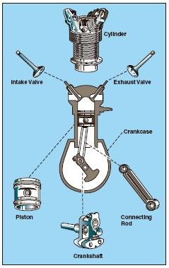
[Figure 5-1. Main components of a reciprocating engine.]
The magnetos are normally located on the engine accessory housing.
The basic principle for reciprocating engines involves the conversion of chemical energy, in the form of fuel, into mechanical energy. This occurs within the cylinders of the engine through a process known as the four-stroke operating cycle. These strokes are called intake, compression, power, and exhaust.
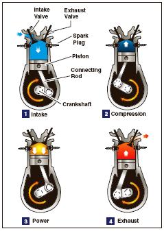
[Figure 5-2 The arrows in this illustration indicate the direction of motion of the crankshaft and piston during the four-stroke cycle.]
1. The intake stroke begins as the piston starts its downward travel. When this happens, the intake valve opens and the fuel/air mixture is drawn into the cylinder.
2. The compression stroke begins when the intake valve closes and the piston starts moving back to the top of the cylinder. This phase of the cycle is used to obtain a much greater power output from the fuel/air mixture once it is ignited.
3. The power stroke begins when the fuel/air mixture is ignited. This causes a tremendous pressure increase in the cylinder, and forces the piston downward away from the cylinder head, creating the power that turns the crankshaft.
4. The exhaust stroke is used to purge the cylinder of burned gases. It begins when the exhaust valve opens and the piston starts to move toward the cylinder head once again.
Even when the engine is operated at a fairly low speed, the four-stroke cycle takes place several hundred times each minute. In a four-cylinder engine, each cylinder operates on a different stroke. Continuous rotation of a crankshaft is maintained by the precise timing of the power strokes in each cylinder. Continuous operation of the engine depends on the simultaneous function of auxiliary systems, including the induction, ignition, fuel, oil, cooling, and exhaust systems.
PROPELLER
The propeller is a rotating airfoil, subject to induced drag, stalls, and other aerodynamic principles that apply to any airfoil. It provides the necessary thrust to pull, or in some cases push, the airplane through the air. The engine power is used to rotate the propeller, which in turn generates thrust very similar to the manner in which a wing produces lift. The amount of thrust produced depends on the shape of the airfoil, the angle of attack of the propeller blade, and the r.p.m. of the engine. The propeller itself is twisted so the blade angle changes from hub to tip. The greatest angle of incidence, or the highest pitch, is at the hub while the smallest pitch is at the tip.
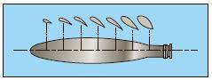
[Figure 5-3. Changes in propeller blade angle from hub to tip.]
The reason for the twist is to produce uniform lift from the hub to the tip. As the blade rotates, there is a difference in the actual speed of the various portions of the blade. The tip of the blade travels faster than that part near the hub, because the tip travels a greater distance than the hub in the same length of time. Changing the angle of incidence (pitch) from the hub to the tip to correspond with the speed produces uniform lift throughout the length of the blade. If the propeller blade was designed with the same angle of incidence throughout its entire length, it would be inefficient, because as airspeed increases in flight, the portion near the hub would have a negative angle of attack while the blade tip would be stalled.
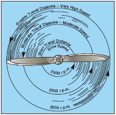
[Figure 5-4 Relationship of travel distance and speed of various portions of propeller blade.]
Small airplanes are equipped with either one of two types of propellers. One is the fixed-pitch, and the other is the controllable-pitch.
FIXED-PITCH PROPELLER
The pitch of this propeller is set by the manufacturer, and cannot be changed. With this type of propeller, the best efficiency is achieved only at a given combination of airspeed and r.p.m. There are two types of fixed-pitch propellers—the climb propeller and the cruise propeller. Whether the airplane has a climb or cruise propeller installed depends upon its intended use:
• The climb propeller has a lower pitch, therefore less drag. Less drag results in higher r.p.m. and more horsepower capability, which increases performance during takeoffs and climbs, but decreases performance during cruising flight.
• The cruise propeller has a higher pitch, therefore more drag. More drag results in lower r.p.m. and less horsepower capability, which decreases performance during takeoffs and climbs, but increases efficiency during cruising flight.
The propeller is usually mounted on a shaft, which may be an extension of the engine crankshaft. In this case, the r.p.m. of the propeller would be the same as the crankshaft r.p.m. On some engines, the propeller is mounted on a shaft geared to the engine crankshaft. In this type, the r.p.m. of the propeller is different than that of the engine. In a fixed-pitch propeller, the tachometer is the indicator of engine power.
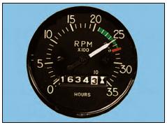
[Figure 5-5. Engine r.p.m. is indicated on the tachometer.]
A tachometer is calibrated in hundreds of r.p.m., and gives a direct indication of the engine and propeller r.p.m. The instrument is color-coded, with a green arc denoting the maximum continuous operating r.p.m. Some tachometers have additional markings to reflect engine and/or propeller limitations. Therefore, the manufacturer’s recommendations should be used as a reference to clarify any misunderstanding of tachometer markings.
The revolutions per minute are regulated by the throttle, which controls the fuel/air flow to the engine. At a given altitude, the higher the tachometer reading, the higher the power output of the engine.
When operating altitude increases, the tachometer may not show correct power output of the engine. For example, 2,300 r.p.m. at 5,000 feet produce less horsepower than 2,300 r.p.m. at sea level. The reason for this is that power output depends on air density. Air density decreases as altitude increases. Therefore, a decrease in air density (higher density altitude) decreases the power output of the engine. As altitude changes, the position of the throttle must be changed to maintain the same r.p.m. As altitude is increased, the throttle must be opened further to indicate the same r.p.m. as at a lower altitude.
ADJUSTABLE-PITCH PROPELLER
Although some older adjustable-pitch propellers could only be adjusted on the ground, most modern adjustable-pitch propellers are designed so that you can change the propeller pitch in flight. The first adjustable-pitch propeller systems provided only two pitch settingsa low-pitch setting and a high-pitch setting. Today, however, nearly all adjustable-pitch propeller systems are capable of a range of pitch settings.
A constant-speed propeller is the most common type of adjustable-pitch propeller. The main advantage of a constant-speed propeller is that it converts a high percentage of brake horsepower (BHP) into thrust horsepower (THP) over a wide range of r.p.m. and airspeed combinations. A constant-speed propeller is more efficient than other propellers because it allows selection of the most efficient engine r.p.m. for the given conditions.
An airplane with a constant-speed propeller has two controls—the throttle and the propeller control. The throttle controls power output, and the propeller control regulates engine r.p.m. and, in turn, propeller r.p.m., which is registered on the tachometer.
Once a specific r.p.m. is selected, a governor automatically adjusts the propeller blade angle as necessary to maintain the selected r.p.m. For example, after setting the desired r.p.m. during cruising flight, an increase in airspeed or decrease in propeller load will cause the propeller blade angle to increase as necessary to maintain the selected r.p.m. A reduction in airspeed or increase in propeller load will cause the propeller blade angle to decrease.
The range of possible blade angles for a constant-speed propeller is the propeller’s constant-speed range and is defined by the high and low pitch stops. As long as the propeller blade angle is within the constant-speed range and not against either pitch stop, a constant engine r.p.m. will be maintained. However, once the propeller blades contact a pitch stop, the engine r.p.m. will increase or decrease as appropriate, with changes in airspeed and propeller load. For example, once a specific r.p.m. has been selected, if aircraft speed decreases enough to rotate the propeller blades until they contact the low pitch stop, any further decrease in airspeed will cause engine r.p.m. to decrease the same way as if a fixed-pitch propeller were installed. The same holds true when an airplane equipped with a constant-speed propeller accelerates to a faster airspeed. As the aircraft accelerates, the propeller blade angle increases to maintain the selected r.p.m. until the high pitch stop is reached. Once this occurs, the blade angle cannot increase any further and engine r.p.m. increases.
On airplanes that are equipped with a constant-speed propeller, power output is controlled by the throttle and indicated by a manifold pressure gauge. The gauge measures the absolute pressure of the fuel/air mixture inside the intake manifold and is more correctly a measure of manifold absolute pressure (MAP). At a constant r.p.m. and altitude, the amount of power produced is directly related to the fuel/air flow being delivered to the combustion chamber. As you increase the throttle setting, more fuel and air is flowing to the engine; therefore, MAP increases. When the engine is not running, the manifold pressure gauge indicates ambient air pressure (i.e., 29.92 in. Hg). When the engine is started, the manifold pressure indication will decrease to a value less than ambient pressure (i.e., idle at 12 in. Hg). Correspondingly, engine failure or power loss is indicated on the manifold gauge as an increase in manifold pressure to a value corresponding to the ambient air pressure at the altitude where the failure occurred.
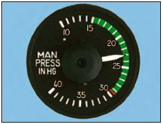
[Figure 5-6 Engine power output is indicated on the manifold pressure gauge.]
The manifold pressure gauge is color-coded to indicate the engine’s operating range. The face of the manifold pressure gauge contains a green arc to show the normal operating range, and a red radial line to indicate the upper limit of manifold pressure.
For any given r.p.m., there is a manifold pressure that should not be exceeded. If manifold pressure is excessive for a given r.p.m., the pressure within the cylinders could be exceeded, thus placing undue stress on the cylinders. If repeated too frequently, this stress could weaken the cylinder components, and eventually cause engine failure.
You can avoid conditions that could overstress the cylinders by being constantly aware of the r.p.m., especially when increasing the manifold pressure. Conform to the manufacturer’s recommendations for power settings of a particular engine so as to maintain the proper relationship between manifold pressure and r.p.m.
When both manifold pressure and r.p.m. need to be changed, avoid engine overstress by making power adjustments in the proper order:
• When power settings are being decreased, reduce manifold pressure before reducing r.p.m. If r.p.m. is reduced before manifold pressure, manifold pressure will automatically increase and possibly exceed the manufacturer’s tolerances.
• When power settings are being increased, reverse the order—increase r.p.m. first, then manifold pressure.
• To prevent damage to radial engines, operating time at maximum r.p.m. and manifold pressure must be held to a minimum, and operation at maximum r.p.m. and low manifold pressure must be avoided.
Under normal operating conditions, the most severe wear, fatigue, and damage to high performance reciprocating engines occurs at high r.p.m. and low manifold pressure.
Powerplant—A complete engine and propeller combination with accessories.
Angle of Incidence—For a propeller, it is the angle formed by the chord
line and the reference plane containing the propeller hub. For a wing, it
is the angle formed by the chord line of the wing and the longitudinal
axis of the airplane.
Manifold Absolute Pressure (MAP)—The absolute pressure of the fuel/air mixture within the intake manifold, usually indicated in inches of mercury.
(Courtesy FAA)