Airplane Ground Schools
Knowledge of Flying is Our passion.
Serving the General Aviation Community
NORMAL APPROACH AND LANDING
A normal approach and landing involves the use of procedures for what is considered a normal situation; that is, when engine power is available, the wind is light or the final approach is made directly into the wind, the final approach path has no obstacles, and the landing surface is firm and of ample length to gradually bring the airplane to a stop. The selected landing point should be beyond the runway’s approach threshold but within the first one-third portion of the runway.
The factors involved and the procedures described for the normal approach and landing also have applications to the other-than-normal approaches and landings which are discussed later in this chapter. This being the case, the principles of normal operations are explained first and must be understood before proceeding to the more complex operations. So that the pilot may better understand the factors that will influence judgment and procedures, that last part of the approach pattern and the actual landing will be divided into five phases: the base leg, the final approach, the roundout, the touchdown, and the after-landing roll.
It must be remembered that the manufacturer’s recommended procedures, including airplane configuration and airspeeds, and other information relevant to approaches and landings in a specific make and model airplane are contained in the FAA-approved Airplane Flight Manual and/or Pilot’s Operating Handbook (AFM/POH) for that airplane. If any of the information in this chapter differs from the airplane manufacturer’s recommendations as contained in the AFM/POH, the airplane manufacturer’s recommendations take precedence.
BASE LEG
The placement of the base leg is one of the more important judgments made by the pilot in any landing approach.
[Figure 8-1 Base leg and final approach]
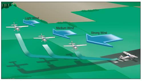
The pilot must accurately judge the altitude and distance from which a gradual descent will result in landing at the desired spot. The distance will depend on the altitude of the base leg, the effect of wind, and the amount of wing flaps used. When there is a strong wind on final approach or the flaps will be used to produce a steep angle of descent, the base leg must be positioned closer to the approach end of the runway than would be required with a light wind or no Figure 8-1. Base leg and final approach. flaps. Normally, the landing gear should be extended and the before landing check completed prior to reaching the base leg.
After turning onto the base leg, the pilot should start the descent with reduced power and airspeed of approximately 1.4 VSO. (VSO—the stalling speed with power off, landing gears and flaps down.) For example, if VSO is 60 knots, the speed should be 1.4 times 60, or 84 knots. Landing flaps may be partially lowered, if desired, at this time. Full flaps are not recommended until the final approach is established. Drift correction should be established and maintained to follow a ground track perpendicular to the extension of the centerline of the runway on which the landing is to be made. Since the final approach and landing will normally be made into the wind, there will be somewhat of a crosswind during the base leg. This requires that the airplane be angled sufficiently into the wind to prevent drifting farther away from the intended landing spot.
The base leg should be continued to the point where a medium to shallow-banked turn will align the airplane’s path directly with the centerline of the landing runway. This descending turn should be completed at a safe altitude that will be dependent upon the height of the terrain and any obstructions along the ground track. The turn to the final approach should also be sufficiently above the airport elevation to permit a final approach long enough for the pilot to accurately estimate the resultant point of touchdown, while maintaining the proper approach airspeed. This will require careful planning as to the starting point and the radius of the turn. Normally, it is recommended that the angle of bank not exceed a medium bank because the steeper the angle of bank, the higher the airspeed at which the airplane stalls. Since the base-tofinal turn is made at a relatively low altitude, it is important that a stall not occur at this point. If an extremely steep bank is needed to prevent overshooting the proper final approach path, it is advisable to discontinue the approach, go around, and plan to start the turn earlier on the next approach rather than risk a hazardous situation.
FINAL APPROACH
After the base-to-final approach turn is completed, the longitudinal axis of the airplane should be aligned with the centerline of the runway or landing surface, so that drift (if any) will be recognized immediately. On a normal approach, with no wind drift, the longitudinal axis should be kept aligned with the runway centerline throughout the approach and landing. (The proper way to correct for a crosswind will be explained under the section, Crosswind Approach and Landing. For now, only an approach and landing where the wind is straight down the runway will be discussed.)
After aligning the airplane with the runway centerline, the final flap setting should be completed and the pitch attitude adjusted as required for the desired rate of descent. Slight adjustments in pitch and power may be necessary to maintain the descent attitude and the desired approach airspeed. In the absence of the manufacturer’s recommended airspeed, a speed equal to 1.3 VSO should be used. If VSO is 60 knots, the speed should be 78 knots. When the pitch attitude and airspeed have been stabilized, the airplane should be retrimmed to relieve the pressures being held on the controls.
The descent angle should be controlled throughout the approach so that the airplane will land in the center of the first third of the runway. The descent angle is affected by all four fundamental forces that act on an airplane (lift, drag, thrust, and weight). If all the forces are constant, the descent angle will be constant in a no-wind condition. The pilot can control these forces by adjusting the airspeed, attitude, power, and drag (flaps or forward slip). The wind also plays a prominent part in the gliding distance over the ground; naturally, the pilot does not have control over the wind but may correct for its effect on the airplane’s descent by appropriate pitch and power adjustments.
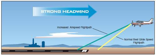
[Figure 8-2 Effect of headwind on final approach]
Considering the factors that affect the descent angle on the final approach, for all practical purposes at a given pitch attitude there is only one power setting for one airspeed, one flap setting, and one wind condition. A change in any one of these variables will require an appropriate coordinated change in the other controllable variables. For example, if the pitch attitude is raised too high without an increase of power, the airplane will settle very rapidly and touch down short of the desired spot. For this reason, the pilot should never try to stretch a glide by applying backelevator pressure alone to reach the desired landing spot. This will shorten the gliding distance if power is not added simultaneously. The proper angle of descent and airspeed should be maintained by coordinating pitch attitude changes and power changes.
The objective of a good final approach is to descend at an angle and airspeed that will permit the airplane to reach the desired touchdown point at an airspeed which will result in minimum floating just before touchdown; in essence, a semi-stalled condition. To accomplish this, it is essential that both the descent angle and the airspeed be accurately controlled. Since on a normal approach the power setting is not fixed as in a power-off approach, the power and pitch attitude should be adjusted simultaneously as necessary, to control the airspeed, and the descent angle, or to attain the desired altitudes along the approach path. By lowering the nose and reducing power to keep approach airspeed constant, a descent at a higher rate can be made to correct for being too high in the approach. This is one reason for performing approaches with partial power; if the approach is too high, merely lower the nose and reduce the power. When the approach is too low, add power and raise the nose.
USE OF FLAPS
The lift/drag factors may also be varied by the pilot to adjust the descent through the use of landing flaps.
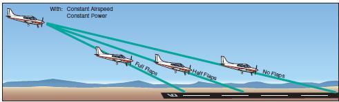
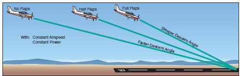
[Figure 8-3 Effect of flaps on the landing point.]
Flap extension during landings provides several advantages by:
• Producing greater lift and permitting lower landing speed.
• Producing greater drag, permitting a steep descent angle without airspeed increase.
• Reducing the length of the landing roll.
Flap extension has a definite effect on the airplane’s pitch behavior. The increased camber from flap deflection produces lift primarily on the rear portion of the wing. This produces a nosedown pitching moment; however, the change in tail loads from the downwash deflected by the flaps over the horizontal tail has a significant influence on the pitching moment. Consequently, pitch behavior depends on the design features of the particular airplane.
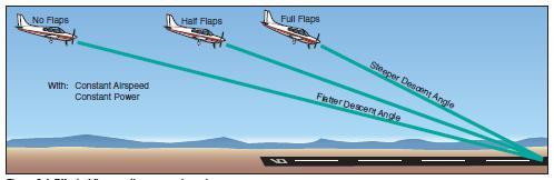
[Figure 8-4. Effect of flaps on the approach angle. ]
Flap deflection of up to 15° primarily produces lift with minimal drag. The airplane has a tendency to balloon up with initial flap deflection because of the lift increase. The nosedown pitching moment, however, tends to offset the balloon. Flap deflection beyond 15° produces a large increase in drag. Also, deflection beyond 15° produces a significant noseup pitching moment in high-wing airplanes because the resulting downwash increases the airflow over the horizontal tail.
The time of flap extension and the degree of deflection are related. Large flap deflections at one single point in the landing pattern produce large lift changes that require significant pitch and power changes in order to maintain airspeed and descent angle. Consequently, the deflection of flaps at certain positions in the landing pattern has definite advantages. Incremental deflection of flaps on downwind, base leg, and final approach allow smaller adjustment of pitch and power compared to extension of full flaps all at one time.
When the flaps are lowered, the airspeed will decrease unless the power is increased or the pitch attitude lowered. On final approach, therefore, the pilot must estimate where the airplane will land through discerning judgment of the descent angle. If it appears that the airplane is going to overshoot the desired landing spot, more flaps may be used if not fully extended or the power reduced further, and the pitch attitude lowered. This will result in a steeper approach. If the desired landing spot is being undershot and a shallower approach is needed, both power and pitch attitude should be increased to readjust the descent angle. Never retract the flaps to correct for undershooting since that will suddenly decrease the lift and cause the airplane to sink even more rapidly.
The airplane must be retrimmed on the final approach to compensate for the change in aerodynamic forces. With the reduced power and with a slower airspeed, the airflow produces less lift on the wings and less downward force on the horizontal stabilizer, resulting in a significant nosedown tendency. The elevator must then be trimmed more noseup.
It will be found that the roundout, touchdown, and landing roll are much easier to accomplish when they are preceded by a proper final approach with precise control of airspeed, attitude, power, and drag resulting in a stabilized descent angle.
ESTIMATING HEIGHT AND MOVEMENT
During the approach, roundout, and touchdown, vision is of prime importance. To provide a wide scope of vision and to foster good judgment of height and movement, the pilot’s head should assume a natural, straight-ahead position. The pilot’s visual focus should not be fixed on any one side or any one spot ahead of the airplane, but should be changing slowly from a point just over the airplane’s nose to the desired touchdown zone and back again, while maintaining a deliberate awareness of distance from either side of the runway within the pilot’s peripheral field of vision.
Accurate estimation of distance is, besides being a matter of practice, dependent upon how clearly objects are seen; it requires that the vision be focused properly in order that the important objects stand out as clearly as possible.
Speed blurs objects at close range. For example, most everyone has noted this in an automobile moving at high speed. Nearby objects seem to merge together in a blur, while objects farther away stand out clearly. The driver subconsciously focuses the eyes sufficiently far ahead of the automobile to see objects distinctly. The distance at which the pilot’s vision is focused should be proportionate to the speed at which the airplane is traveling over the ground. Thus, as speed is reduced during the roundout, the distance ahead of the airplane at which it is possible to focus should be brought closer accordingly.
[Figure 8-5 Focusing too close blurs vision]
If the pilot attempts to focus on a reference that is too close or looks directly down, the reference will become blurred, and the reaction will be either too abrupt or too late. In this case, the pilot’s tendency will be to overcontrol, round out high, and make full-stall, drop-in landings. When the pilot focuses too far ahead, accuracy in judging the closeness of the ground is lost and the consequent reaction will be too slow since there will not appear to be a necessity for action. This will result in the airplane flying into the ground nose first. The change of visual focus from a long distance to a short distance requires a definite time interval and even though the time is brief, the airplane’s speed during this interval is such that the airplane travels an appreciable distance, both forward and downward toward the ground.
If the focus is changed gradually, being brought progressively closer as speed is reduced, the time interval and the pilot’s reaction will be reduced, and the whole landing process smoothed out.
ROUNDOUT (FLARE)
The roundout is a slow, smooth transition from a normal approach attitude to a landing attitude, gradually rounding out the flightpath to one that is parallel with, and within a very few inches above, the runway. When the airplane, in a normal descent, approaches within what appears to be 10 to 20 feet above the ground, the roundout or flare should be started, and once started should be a continuous process until the airplane touches down on the ground.
As the airplane reaches a height above the ground where a timely change can be made into the proper landing attitude, back-elevator pressure should be gradually applied to slowly increase the pitch attitude and angle of attack.
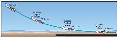
[Figure 8-6 Changing angle of attack during roundout]
This will cause the airplane’s nose to gradually rise toward the desired landing attitude. The angle of attack should be increased at a rate that will allow the airplane to continue settling slowly as forward speed decreases.
When the angle of attack is increased, the lift is momentarily increased, which decreases the rate of descent. Since power normally is reduced to idle during the roundout, the airspeed will also gradually decrease. This will cause lift to decrease again, and it must be controlled by raising the nose and further increasing the angle of attack. During the roundout, the airspeed is being decreased to touchdown speed while the lift is being controlled so the airplane will settle gently onto the landing surface. The roundout should be executed at a rate that the proper landing attitude and the proper touchdown airspeed are attained simultaneously just as the wheels contact the landing surface.
The rate at which the roundout is executed depends on the airplane’s height above the ground, the rate of descent, and the pitch attitude. A roundout started excessively high must be executed more slowly than one from a lower height to allow the airplane to descend to the ground while the proper landing attitude is being established. The rate of rounding out must also be proportionate to the rate of closure with the ground. When the airplane appears to be descending very slowly, the increase in pitch attitude must be made at a correspondingly slow rate.
Visual cues are important in flaring at the proper altitude and maintaining the wheels a few inches above the runway until eventual touchdown. Flare cues are primarily dependent on the angle at which the pilot’s central vision intersects the ground (or runway) ahead and slightly to the side. Proper depth perception is a factor in a successful flare, but the visual cues used most are those related to changes in runway or terrain perspective and to changes in the size of familiar objects near the landing area such as fences, bushes, trees, hangars, and even sod or runway texture. The pilot should direct central vision at a shallow downward angle of from 10° to 15° toward the runway as the roundout/flare is initiated.
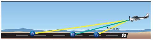
[Figure 8-7 To obtain necessary visual cues, the pilot should look toward the runway at a shallow angle]
Maintaining the same viewing angle causes the point of visual interception with the runway to move progressively rearward toward the pilot as the airplane loses altitude. This is an important visual cue in assessing the rate of altitude loss. Conversely, forward movement of the visual interception point will indicate an increase in altitude, and would mean that the pitch angle was increased too rapidly, resulting in an over flare. Location of the visual interception point in conjunction with assessment of flow velocity of nearby off-runway terrain, as well as the similarity of appearance of height above the runway ahead of the airplane (in comparison to the way it looked when the airplane was taxied prior to takeoff) is also used to judge when the wheels are just a few inches above the runway.
The pitch attitude of the airplane in a full-flap approach is considerably lower than in a no-flap approach. To attain the proper landing attitude before touching down, the nose must travel through a greater pitch change when flaps are fully extended. Since the roundout is usually started at approximately the same height above the ground regardless of the degree of flaps used, the pitch attitude must be increased at a faster rate when full flaps are used; however, the roundout should still be executed at a rate proportionate to the airplane’s downward motion.
Once the actual process of rounding out is started, the elevator control should not be pushed forward. If too much back-elevator pressure has been exerted, this pressure should be either slightly relaxed or held constant, depending on the degree of the error. In some cases, it may be necessary to advance the throttle slightly to prevent an excessive rate of sink, or a stall, all of which would result in a hard, drop-in type landing.
It is recommended that the student pilot form the habit of keeping one hand on the throttle throughout the approach and landing, should a sudden and unexpected hazardous situation require an immediate application of power.
TOUCHDOWN
The touchdown is the gentle settling of the airplane onto the landing surface. The roundout and touchdown should be made with the engine idling, and the airplane at minimum controllable airspeed, so that the airplane will touch down on the main gear at approximately stalling speed. As the airplane settles, the proper landing attitude is attained by application of whatever back-elevator pressure is necessary.
Some pilots may try to force or fly the airplane onto the ground without establishing the proper landing attitude. The airplane should never be flown on the runway with excessive speed. It is paradoxical that the way to make an ideal landing is to try to hold the airplane’s wheels a few inches off the ground as long as possible with the elevators. In most cases, when the wheels are within 2 or 3 feet off the ground, the airplane will still be settling too fast for a gentle touchdown; therefore, this descent must be retarded by further back-elevator pressure. Since the airplane is already close to its stalling speed and is settling, this added back-elevator pressure will only slow up the settling instead of stopping it. At the same time, it will result in the airplane touching the ground in the proper landing attitude, and the main wheels touching down first so that little or no weight is on the nosewheel.
[Figure 8-8 A well executed roundout results in attaining the proper landing attitude]
After the main wheels make initial contact with the ground, back-elevator pressure should be held to maintain a positive angle of attack for aerodynamic braking, and to hold the nosewheel off the ground until the airplane decelerates. As the airplane’s momentum decreases, back-elevator pressure may be gradually relaxed to allow the nosewheel to gently settle onto the runway. This will permit steering with the nosewheel. At the same time, it will cause a low angle of attack and negative lift on the wings to prevent floating or skipping, and will allow the full weight of the airplane to rest on the wheels for better braking action.
A well executed roundout results in attaining the proper landing attitude. It is extremely important that the touchdown occur with the airplane’s longitudinal axis exactly parallel to the direction in which the airplane is moving along the runway. Failure to accomplish this imposes severe side loads on the landing gear. To avoid these side stresses, the pilot should not allow the airplane to touch down while turned into the wind or drifting.
AFTER-LANDING ROLL
The landing process must never be considered complete until the airplane decelerates to the normal taxi speed during the landing roll or has been brought to a complete stop when clear of the landing area. Many accidents have occurred as a result of pilots abandoning their vigilance and positive control after getting the airplane on the ground.
The pilot must be alert for directional control difficulties immediately upon and after touchdown due to the ground friction on the wheels. The friction creates a pivot point on which a moment arm can act. Loss of directional control may lead to an aggravated, uncontrolled, tight turn on the ground, or a ground loop. The combination of centrifugal force acting on the center of gravity (CG) and ground friction of the main wheels resisting it during the ground loop may cause the airplane to tip or lean enough for the outside wingtip to contact the ground. This may even impose a sideward force, which could collapse the landing gear.
The rudder serves the same purpose on the ground as it does in the air—it controls the yawing of the airplane. The effectiveness of the rudder is dependent on the airflow, which depends on the speed of the airplane. As the speed decreases and the nosewheel has been lowered to the ground, the steerable nose provides more positive directional control.
The brakes of an airplane serve the same primary purpose as the brakes of an automobile—to reduce speed on the ground. In airplanes, they may also be used as an aid in directional control when more positive control is required than could be obtained with rudder or nosewheel steering alone.
To use brakes, on an airplane equipped with toe brakes, the pilot should slide the toes or feet up from the rudder pedals to the brake pedals. If rudder pressure is being held at the time braking action is needed, that pressure should not be released as the feet or toes are being slid up to the brake pedals, because control may be lost before brakes can be applied.
Putting maximum weight on the wheels after touchdown is an important factor in obtaining optimum braking performance. During the early part of rollout, some lift may continue to be generated by the wing. After touchdown, the nosewheel should be lowered to the runway to maintain directional control. During deceleration, the nose may be pitched down by braking and the weight transferred to the nosewheel from the main wheels. This does not aid in braking action, so back pressure should be applied to the controls without lifting the nosewheel off the runway. This will enable the pilot to maintain directional control while keeping weight on the main wheels.
Careful application of the brakes can be initiated after the nosewheel is on the ground and directional control is established. Maximum brake effectiveness is just short of the point where skidding occurs. If the brakes are applied so hard that skidding takes place, braking becomes ineffective. Skidding can be stopped by releasing the brake pressure. Also, braking effectiveness is not enhanced by alternately applying and reapplying brake pressure. The brakes should be applied firmly and smoothly as necessary.
During the ground roll, the airplane’s direction of movement can be changed by carefully applying pressure on one brake or uneven pressures on each brake in the desired direction. Caution must be exercised when applying brakes to avoid overcontrolling.
The ailerons serve the same purpose on the ground as they do in the air—they change the lift and drag components of the wings. During the after-landing roll, they should be used to keep the wings level in much the same way they were used in flight. If a wing starts to rise, aileron control should be applied toward that wing to lower it. The amount required will depend on speed because as the forward speed of the airplane decreases, the ailerons will become less effective. Procedures for using ailerons in crosswind conditions are explained further in this chapter, in the Crosswind Approach and Landing section.
After the airplane is on the ground, back-elevator pressure may be gradually relaxed to place normal weight on the nosewheel to aid in better steering. If available runway permits, the speed of the airplane should be allowed to dissipate in a normal manner. Once the airplane has slowed sufficiently and has turned on to the taxiway and stopped, the pilot should retract the flaps and clean up the airplane. Many accidents have occurred as a result of the pilot unintentionally operating the landing gear control and retracting the gear instead of the flap control when the airplane was still rolling. The habit of positively identifying both of these controls, before actuating them, should be formed from the very beginning of flight training and continued in all future flying activities.
STABILIZED APPROACH CONCEPT
A stabilized approach is one in which the pilot establishes and maintains a constant angle glidepath towards a predetermined point on the landing runway. It is based on the pilot’s judgment of certain visual clues, and depends on the maintenance of a constant final descent airspeed and configuration. An airplane descending on final approach at a constant rate and airspeed will be traveling in a straight line toward a spot on the ground ahead. This spot will not be the spot on which the airplane will touch down, because some float will inevitably occur during the roundout (flare).
Neither will it be the spot toward which the airplane’s nose is pointed, because the airplane is flying at a fairly high angle of attack, and the component of lift exerted parallel to the Earth’s surface by the wings tends to carry the airplane forward horizontally.
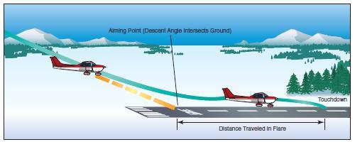
The point toward which the airplane is progressing is termed the “aiming point.”
[Figure 8-9 Stabilized approach]
It is the point on the ground at which, if the airplane maintains a constant glidepath, and was not flared for landing, it would strike the ground. To a pilot moving straight ahead toward an object, it appears to be stationary. It does not “move.” This is how the aiming point can be distinguished—it does not move. However, objects in front of and beyond the aiming point do appear to move as the distance is closed, and they appear to move in opposite directions. During instruction in landings, one of the most important skills a student pilot must acquire is how to use visual cues to accurately determine the true aiming point from any distance out on final approach. From this, the pilot will not only be able to determine if the glidepath will result in an undershoot or overshoot, but, taking into account float during roundout, the pilot will be able to predict the touchdown point to within a very few feet.
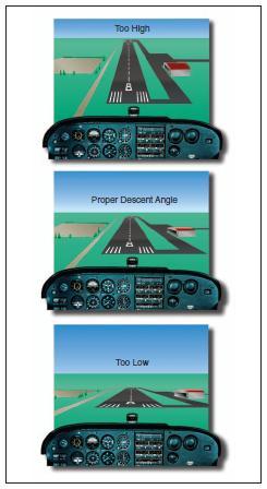
For a constant angle glidepath, the distance between the horizon and the aiming point will remain constant. If a final approach descent has been established but the distance between the perceived aiming point and the horizon appears to increase (aiming point moving down away from the horizon), then the true aiming point, and subsequent touchdown point, is farther down the runway. If the distance between the perceived aiming point and the horizon decreases (aiming point moving up toward the horizon), the true aiming point is closer than perceived.
When the airplane is established on final approach, the shape of the runway image also presents clues as to what must be done to maintain a stabilized approach to a safe landing.
A runway, obviously, is normally shaped in the form of an elongated rectangle. When viewed from the air during the approach, the phenomenon known as perspective causes the runway to assume the shape of a trapezoid with the far end looking narrower than the approach end, and the edge lines converging ahead. If the airplane continues down the glidepath at a constant angle (stabilized), the image the pilot sees will still be trapezoidal but of proportionately larger dimensions. In other words, during a stabilized approach the runway shape does not change.
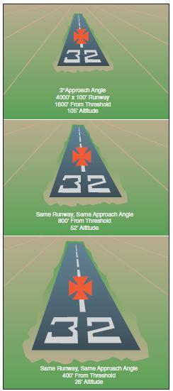
[Figure 8-10 Runway shape during stabilized approach.]
If the approach becomes shallower, however, the runway will appear to shorten and become wider. Conversely, if the approach is steepened, the runway will appear to become longer and narrower.
[Figure 8-11 Change in runway shape if approach becomes
narrow or steep]
The objective of a stabilized approach is to select an appropriate touchdown point on the runway, and adjust the glidepath so that the true aiming point and the desired touchdown point basically coincide. Immediately after rolling out on final approach, the pilot should adjust the pitch attitude and power so that the airplane is descending directly toward the aiming point at the appropriate airspeed. The airplane should be in the landing configuration, and trimmed for “hands off” flight. With the approach set up in this manner, the pilot will be free to devote full attention toward outside references. The pilot should not stare at any one place, but rather scan from one point to another, such as from the aiming point to the horizon, to the trees and bushes along the runway, to an area well short of the runway, and back to the aiming point. In this way, the pilot will be more apt to perceive a deviation from the desired glidepath, and whether or not the airplane is proceeding directly toward the aiming point.
If the pilot perceives any indication that the aiming point on the runway is not where desired, an adjustment must be made to the glidepath. This in turn will move the aiming point. For instance, if the pilot perceives that the aiming point is short of the desired touchdown point and will result in an undershoot, an increase in pitch attitude and engine power is warranted. Aconstant airspeed must be maintained. The pitch and power change, therefore, must be made smoothly and simultaneously. This will result in a shallowing of the glidepath with the resultant aiming point moving towards the desired touchdown point. Conversely, if the pilot perceives that the aiming point is farther down the runway than the desired touchdown point and will result in an overshoot, the glidepath should be steepened by a simultaneous decrease in pitch attitude and power. Once again, the airspeed must be held constant. It is essential that deviations from the desired glidepath be detected early, so that only slight and infrequent adjustments to glidepath are required.
The closer the airplane gets to the runway, the larger (and possibly more frequent) the required corrections become, resulting in an unstabilized approach.
Common errors in the performance of normal approaches and landings are:
• Inadequate wind drift correction on the base leg.
• Overshooting or undershooting the turn onto final approach resulting in too steep or too shallow a turn onto final approach.
• Flat or skidding turns from base leg to final approach as a result of overshooting/inadequate wind drift correction.
• Poor coordination during turn from base to final approach.
• Failure to complete the landing checklist in a timely manner.
• Unstabilized approach.
• Failure to adequately compensate for flap extension.
• Poor trim technique on final approach.
• Attempting to maintain altitude or reach the runway using elevator alone.
• Focusing too close to the airplane resulting in a too high roundout.
• Focusing too far from the airplane resulting in a too low roundout.
• Touching down prior to attaining proper landing attitude.
• Failure to hold sufficient back-elevator pressure after touchdown.
• Excessive braking after touchdown.
INTENTIONAL SLIPS
A slip occurs when the bank angle of an airplane is too steep for the existing rate of turn. Unintentional slips are most often the result of uncoordinated rudder/aileron application. Intentional slips, however, are used to dissipate altitude without increasing airspeed, and/or to adjust airplane ground track during a crosswind. Intentional slips are especially useful in forced landings, and in situations where obstacles must be cleared during approaches to confined areas. A slip can also be used as an emergency means of rapidly reducing airspeed in situations where wing flaps are inoperative or not installed.
A slip is a combination of forward movement and sideward (with respect to the longitudinal axis of the airplane) movement, the lateral axis being inclined and the sideward movement being toward the low end of this axis (low wing). An airplane in a slip is in fact flying sideways. This results in a change in the direction the relative wind strikes the airplane. Slips are characterized by a marked increase in drag and corresponding decrease in airplane climb, cruise, and glide performance. It is the increase in drag, however, that makes it possible for an airplane in a slip to descend rapidly without an increase in airspeed.
Most airplanes exhibit the characteristic of positive static directional stability and, therefore, have a natural tendency to compensate for slipping. An intentional slip, therefore, requires deliberate cross-controlling ailerons and rudder throughout the maneuver.
A“sideslip” is entered by lowering a wing and applying just enough opposite rudder to prevent a turn. In a sideslip, the airplane’s longitudinal axis remains parallel to the original flightpath, but the airplane no longer flies straight ahead. Instead the horizontal component of wing lift forces the airplane also to move somewhat sideways toward the low wing.
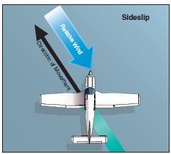
[Figure 8-12 Sideslip]
The amount of slip, and therefore the rate of sideward movement, is determined by the bank angle. The steeper the bank—the greater the degree of slip. As bank angle is increased, however, additional opposite rudder is required to prevent turning.
A “forward slip” is one in which the airplane’s direction of motion continues the same as before the slip was begun. Assuming the airplane is originally in straight flight, the wing on the side toward which the slip is to be made should be lowered by use of the ailerons. Simultaneously, the airplane’s nose must be yawed in the opposite direction by applying opposite rudder so that the airplane’s longitudinal axis is at an angle to its original flightpath.
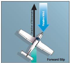
[Figure 8-13 Forward slip.]
The degree to which the nose is yawed in the opposite direction from the bank should be such that the original ground track is maintained. In a forward slip, the amount of slip, and therefore the sink rate, is determined by the bank angle. The steeper the bank— the steeper the descent.
In most light airplanes, the steepness of a slip is limited by the amount of rudder travel available. In both sideslips and forward slips, the point may be reached where full rudder is required to maintain heading even though the ailerons are capable of further steepening the bank angle. This is the practical slip limit, because any additional bank would cause the airplane to turn even though full opposite rudder is being applied. If there is a need to descend more rapidly even though the practical slip limit has been reached, lowering the nose will not only increase the sink rate but will also increase airspeed. The increase in airspeed increases rudder effectiveness permitting a steeper slip. Conversely, when the nose is raised, rudder effectiveness decreases and the bank angle must be reduced.
Discontinuing a slip is accomplished by leveling the wings and simultaneously releasing the rudder pressure while readjusting the pitch attitude to the normal glide attitude. If the pressure on the rudder is released abruptly, the nose will swing too quickly into line and the airplane will tend to acquire excess speed.
Because of the location of the pitot tube and static vents, airspeed indicators in some airplanes may have considerable error when the airplane is in a slip. The pilot must be aware of this possibility and recognize a properly performed slip by the attitude of the airplane, the sound of the airflow, and the feel of the flight controls. Unlike skids, however, if an airplane in a slip is made to stall, it displays very little of the yawing tendency that causes a skidding stall to develop into a spin. The airplane in a slip may do little more than tend to roll into a wings level attitude. In fact, in some airplanes stall characteristics may even be improved.
GO-AROUNDS
(REJECTED LANDINGS)
Whenever landing conditions are not satisfactory, a go-around is warranted. There are many factors that can contribute to unsatisfactory landing conditions. Situations such as air traffic control requirements, unexpected appearance of hazards on the runway, overtaking another airplane, wind shear, wake turbulence, mechanical failure and/or an unstabilized approach are all examples of reasons to discontinue a landing approach and make another approach under more favorable conditions. The assumption that an aborted landing is invariably the consequence of a poor approach, which in turn is due to insufficient experience or skill, is a fallacy. The go-around is not strictly an emergency procedure. It is a normal maneuver that may at times be used in an emergency situation. Like any other normal maneuver, the go-around must be practiced and perfected. The flight instructor should emphasize early on, and the student pilot should be made to understand, that the go-around maneuver is an alternative to any approach and/or landing.
Although the need to discontinue a landing may arise at any point in the landing process, the most critical go-around will be one started when very close to the ground. Therefore, the earlier a condition that warrants a go-around is recognized, the safer the go-around/rejected landing will be. The go-around maneuver is not inherently dangerous in itself. It becomes dangerous only when delayed unduly or executed improperly. Delay in initiating the go-around normally stems from two sources:
(1) landing expectancy, or set—the anticipatory belief that conditions are not as threatening as they are and that the approach will surely be terminated with a safe landing, and
(2) pride—the mistaken belief that the act of going around is an admission of failure—failure to execute the approach properly.
The improper execution of the goaround maneuver stems from a lack of familiarity with the three cardinal principles of the procedure: power, attitude, and configuration.
POWER
Power is the pilot’s first concern. The instant the pilot decides to go around, full or maximum allowable takeoff power must be applied smoothly and without hesitation, and held until flying speed and controllability are restored. Applying only partial power in a go-around is never appropriate. The pilot must be aware of the degree of inertia that must be overcome, before an airplane that is settling towards the ground can regain sufficient airspeed to become fully controllable and capable of turning safely or climbing. The application of power should be smooth as well as positive. Abrupt movements of the throttle in some airplanes will cause the engine to falter. Carburetor heat should be turned off for maximum power.
ATTITUDE
Attitude is always critical when close to the ground, and when power is added, a deliberate effort on the part of the pilot will be required to keep the nose from pitching up prematurely. The airplane executing a goaround must be maintained in an attitude that permits a buildup of airspeed well beyond the stall point before any effort is made to gain altitude, or to execute a turn. Raising the nose too early may produce a stall from which the airplane could not be recovered if the go-around is performed at a low altitude.
A concern for quickly regaining altitude during a goaround produces a natural tendency to pull the nose up. The pilot executing a go-around must accept the fact that an airplane will not climb until it can fly, and it will not fly below stall speed. In some circumstances, it may be desirable to lower the nose briefly to gain airspeed. As soon as the appropriate climb airspeed and pitch attitude are attained, the pilot should “rough trim” the airplane to relieve any adverse control pressures. Later, more precise trim adjustments can be made when flight conditions have stabilized.
CONFIGURATION
In cleaning up the airplane during the go-around, the pilot should be concerned first with flaps and secondly with the landing gear (if retractable). When the decision is made to perform a go-around, takeoff power should be applied immediately and the pitch attitude changed so as to slow or stop the descent. After the descent has been stopped, the landing flaps may be partially retracted or placed in the takeoff position as recommended by the manufacturer. Caution must be used, however, in retracting the flaps. Depending on the airplane’s altitude and airspeed, it may be wise to retract the flaps intermittently in small increments to allow time for the airplane to accelerate progressively as they are being raised. Asudden and complete retraction of the flaps could cause a loss of lift resulting in the airplane settling into the ground.
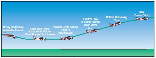
[Figure 8-14 Go-around procedure]
Unless otherwise specified in the AFM/POH, it is generally recommended that the flaps be retracted (at least partially) before retracting the landing gear—for two reasons. First, on most airplanes full flaps produce more drag than the landing gear; and second, in case the airplane should inadvertently touch down as the go-around is initiated, it is most desirable to have the landing gear in the down-and-locked position. After a positive rate of climb is established, the landing gear can be retracted.
When takeoff power is applied, it will usually be necessary to hold considerable pressure on the controls to maintain straight flight and a safe climb attitude. Since the airplane has been trimmed for the approach (a low power and low airspeed condition), application of maximum allowable power will require considerable control pressure to maintain a climb pitch attitude. The addition of power will tend to raise the airplane’s nose suddenly and veer to the left. Forward elevator pressure must be anticipated and applied to hold the nose in a safe climb attitude. Right rudder pressure must be increased to counteract torque and P-factor, and to keep the nose straight. The airplane must be held in the proper flight attitude regardless of the amount of control pressure that is required. Trim should be used to relieve adverse control pressures and assist the pilot in maintaining a proper pitch attitude. On airplanes that produce high control pressures when using maximum power on go-arounds, pilots should use caution when reaching for the flap handle. Airplane control may become critical during this high workload phase.
The landing gear should be retracted only after the initial or rough trim has been accomplished and when it is certain the airplane will remain airborne. During the initial part of an extremely low go-around, the airplane may settle onto the runway and bounce. This situation is not particularly dangerous if the airplane is kept straight and a constant, safe pitch attitude is maintained. The airplane will be approaching safe flying speed rapidly and the advanced power will cushion any secondary touchdown.
If the pitch attitude is increased excessively in an effort to keep the airplane from contacting the runway, it may cause the airplane to stall. This would be especially likely if no trim correction is made and the flaps remain fully extended. The pilot should not attempt to retract the landing gear until after a rough trim is accomplished and a positive rate of climb is established.
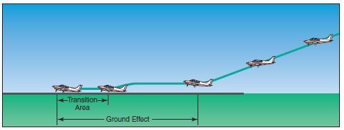
GROUND EFFECT
Ground effect is a factor in every landing and every takeoff in fixed-wing airplanes. Ground effect can also be an important factor in go-arounds. If the go-around is made close to the ground, the airplane may be in the ground effect area. Pilots are often lulled into a sense of false security by the apparent “cushion of air” under the wings that initially assists in the transition from an approach descent to a climb. This “cushion of air,” however, is imaginary. The apparent increase in airplane performance is, in fact, due to a reduction in induced drag in the ground effect area. It is “borrowed” performance that must be repaid when the airplane climbs out of the ground effect area. The pilot must factor in ground effect when initiating a go-around close to the ground. An attempt to climb prematurely may result in the airplane not being able to climb, or even maintain altitude at full power. Common errors in the performance of go-arounds (rejected landings) are:
• Failure to recognize a condition that warrants a rejected landing.
• Indecision.
• Delay in initiating a go-round.
• Failure to apply maximum allowable power in a timely manner.
• Abrupt power application.
• Improper pitch attitude.
• Failure to configure the airplane appropriately.
• Attempting to climb out of ground effect prematurely.
• Failure to adequately compensate for torque/Pfactor.
CROSSWIND APPROACH AND LANDING
Many runways or landing areas are such that landings must be made while the wind is blowing across rather than parallel to the landing direction. All pilots should be prepared to cope with these situations when they arise. The same basic principles and factors involved in a normal approach and landing apply to a crosswind approach and landing; therefore, only the additional procedures required for correcting for wind drift are discussed here. Crosswind landings are a little more difficult to perform than crosswind takeoffs, mainly due to different problems involved in maintaining accurate control of the airplane while its speed is decreasing rather than increasing as on takeoff. There are two usual methods of accomplishing a crosswind approach and landing—the crab method and the wing-low (sideslip) method. Although the crab method may be easier for the pilot to maintain during final approach, it requires a high degree of judgment and timing in removing the crab immediately prior to touchdown. The wing-low method is recommended in most cases, although a combination of both methods may be used.
CROSSWIND FINAL APPROACH
The crab method is executed by establishing a heading (crab) toward the wind with the wings level so that the airplane’s ground track remains aligned with the centerline of the runway.
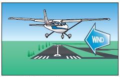
[Figure 8-15 Crabbed approach]
This crab angle is maintained until just prior to touchdown, when the longitudinal axis of the airplane must be aligned with the runway to avoid sideward contact of the wheels with the runway. If a long final approach is being flown, the pilot may use the crab method until just before the roundout is started and then smoothly change to the wing-low method for the remainder of the landing.
The wing-low (sideslip) method will compensate for a crosswind from any angle, but more important, it enables the pilot to simultaneously keep the airplane’s ground track and longitudinal axis aligned with the runway centerline throughout the final approach, roundout, touchdown, and after-landing roll. This prevents the airplane from touching down in a sideward motion and imposing damaging side loads on the landing gear. To use the wing-low method, the pilot aligns the airplane’s heading with the centerline of the runway, notes the rate and direction of drift, and then promptly applies drift correction by lowering the upwind wing.
[Figure 8-16 Sideslip approach]
The amount the wing must be lowered depends on the rate of drift. When the wing is lowered, the airplane will tend to turn in that direction. It is then necessary to simultaneously apply sufficient opposite rudder pressure to prevent the turn and keep the airplane’s longitudinal axis aligned with the runway. In other words, the drift is controlled with aileron, and the heading with rudder. The airplane will now be sideslipping into the wind just enough that both the resultant flightpath and the ground track are aligned with the runway. If the crosswind diminishes, this crosswind correction is reduced accordingly, or the airplane will begin slipping away from the desired approach path.
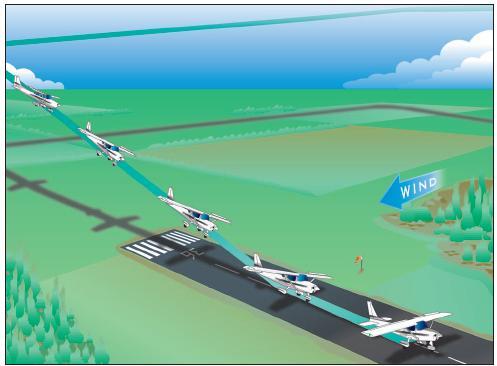
[Figure 8-17 Crosswind approach and landing]
To correct for strong crosswind, the slip into the wind is increased by lowering the upwind wing a considerable amount. As a consequence, this will result in a greater tendency of the airplane to turn. Since turning is not desired, considerable opposite rudder must be applied to keep the airplane’s longitudinal axis aligned with the runway. In some airplanes, there may not be sufficient rudder travel available to compensate for the strong turning tendency caused by the steep bank. If the required bank is such that full opposite rudder will not prevent a turn, the wind is too strong to safely land the airplane on that particular runway with those wind conditions. Since the airplane’s capability will be exceeded, it is imperative that the landing be made on a more favorable runway either at that airport or at an alternate airport.
Flaps can and should be used during most approaches since they tend to have a stabilizing effect on the airplane. The degree to which flaps should be extended will vary with the airplane’s handling characteristics, as well as the wind velocity.
CROSSWIND ROUNDOUT (FLARE)
Generally, the roundout can be made like a normal landing approach, but the application of a crosswind correction is continued as necessary to prevent drifting.
Since the airspeed decreases as the roundout progresses, the flight controls gradually become less effective. As a result, the crosswind correction being held will become inadequate. When using the winglow method, it is necessary to gradually increase the deflection of the rudder and ailerons to maintain the proper amount of drift correction.
Do not level the wings; keep the upwind wing down throughout the roundout. If the wings are leveled, the airplane will begin drifting and the touchdown will occur while drifting. Remember, the primary objective is to land the airplane without subjecting it to any side loads that result from touching down while drifting.
CROSSWIND TOUCHDOWN
If the crab method of drift correction has been used throughout the final approach and roundout, the crab must be removed the instant before touchdown by applying rudder to align the airplane’s longitudinal axis with its direction of movement. This requires timely and accurate action. Failure to accomplish this will result in severe side loads being imposed on the landing gear.
If the wing-low method is used, the crosswind correction (aileron into the wind and opposite rudder) should be maintained throughout the roundout, and the touchdown made on the upwind main wheel.
During gusty or high wind conditions, prompt adjustments must be made in the crosswind correction to assure that the airplane does not drift as the airplane touches down.
As the forward momentum decreases after initial contact, the weight of the airplane will cause the downwind main wheel to gradually settle onto the runway.
In those airplanes having nosewheel steering interconnected with the rudder, the nosewheel may not be aligned with the runway as the wheels touch down because opposite rudder is being held in the crosswind correction. To prevent swerving in the direction the nosewheel is offset, the corrective rudder pressure must be promptly relaxed just as the nosewheel touches down.
CROSSWIND AFTER-LANDING ROLL
Particularly during the after-landing roll, special attention must be given to maintaining directional control by the use of rudder or nosewheel steering, while keeping the upwind wing from rising by the use of aileron. When an airplane is airborne, it moves with the air mass in which it is flying regardless of the airplane’s heading and speed.
When an airplane is on the ground, it is unable to move with the air mass (crosswind) because of the resistance created by ground friction on the wheels.
Characteristically, an airplane has a greater profile or side area, behind the main landing gear than forward of it does. With the main wheels acting as a pivot point and the greater surface area exposed to the crosswind behind that pivot point, the airplane will tend to turn or weathervane into the wind.
Wind acting on an airplane during crosswind landings is the result of two factors. One is the natural wind, which acts in the direction the air mass is traveling, while the other is induced by the movement of the airplane and acts parallel to the direction of movement. Consequently, a crosswind has a headwind component acting along the airplane’s ground track and a crosswind component acting 90° to its track. The resultant or relative wind is somewhere between the two components. As the airplane’s forward speed decreases during the afterlanding roll, the headwind component decreases and the relative wind has more of a crosswind component. The greater the crosswind component, the more difficult it is to prevent weathervaning.
Retaining control on the ground is a critical part of the after-landing roll, because of the weathervaning effect of the wind on the airplane. Additionally, tire side load from runway contact while drifting frequently generates roll-overs in tricycle geared airplanes. The basic factors involved are cornering angle and side load.
Cornering angle is the angular difference between the heading of a tire and its path. Whenever a load bearing tire’s path and heading diverge, a side load is created. It is accompanied by tire distortion. Although side load differs in varying tires and air pressures, it is completely independent of speed, and through a considerable range, is directional proportional to the cornering angle and the weight supported by the tire. As little as 10° of cornering angle will create a side load equal to half the supported weight; after 20° the side load does not increase with increasing cornering angle. For each high-wing, tricycle geared airplane, there is a cornering angle at which roll-over is inevitable. The roll-over axis being the line linking the nose and main wheels. At lesser angles, the roll-over may be avoided by use of ailerons, rudder, or steerable nosewheel but not brakes.
While the airplane is decelerating during the afterlanding roll, more and more aileron is applied to keep the upwind wing from rising. Since the airplane is slowing down, there is less airflow around the ailerons and they become less effective. At the same time, the relative wind is becoming more of a crosswind and exerting a greater lifting force on the upwind wing. When the airplane is coming to a stop, the aileron control must be held fully toward the wind.
MAXIMUM SAFE CROSSWIND VELOCITIES
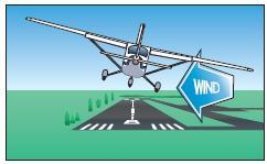
Takeoffs and landings in certain crosswind conditions are inadvisable or even dangerous.
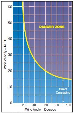
[Figure 8-18 Crosswind chart.]
If the crosswind is great enough to warrant an extreme drift correction, a hazardous landing condition may result. Therefore, the takeoff and landing capabilities with respect to the reported surface wind conditions and the available landing directions must be considered.
Before an airplane is type certificated by the Federal Aviation Administration (FAA), it must be flight tested to meet certain requirements. Among these is the demonstration of being satisfactorily controllable with no exceptional degree of skill or alertness on the part of the pilot in 90° crosswinds up to a velocity equal to 0.2 VSO. This means a windspeed of two-tenths of the airplane’s stalling speed with power off and landing gear/flaps down. Regulations require that the demonstrated crosswind velocity be included on a placard in airplanes certificated after May 3, 1962. The headwind component and the crosswind component for a given situation can be determined by reference to a crosswind component chart.
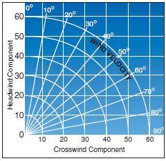
[Figure 8-19 Crosswind component chart.]
It is imperative that pilots determine the maximum crosswind component of each airplane they fly, and avoid operations in wind conditions that exceed the capability of the airplane.
Common errors in the performance of crosswind approaches and landings are:
• Attempting to land in crosswinds that exceed the airplane’s maximum demonstrated crosswind component.
• Inadequate compensation for wind drift on the turn from base leg to final approach, resulting in undershooting or overshooting.
• Inadequate compensation for wind drift on final approach.
• Unstabilized approach.
• Failure to compensate for increased drag during sideslip resulting in excessive sink rate and/or too low an airspeed.
• Touchdown while drifting.
• Excessive airspeed on touchdown.
• Failure to apply appropriate flight control inputs during rollout.
• Failure to maintain direction control on rollout.
• Excessive braking.
TURBULENT AIR APPROACH AND LANDING
Power-on approaches at an airspeed slightly above the normal approach speed should be used for landing in turbulent air. This provides for more positive control of the airplane when strong horizontal wind gusts, or up and down drafts, are experienced. Like other power-on approaches (when the pilot can vary the amount of power), a coordinated combination of both pitch and power adjustments is usually required. As in most other landing approaches, the proper approach attitude and airspeed require a minimum roundout and should result in little or no floating during the landing.
To maintain good control, the approach in turbulent air with gusty crosswind may require the use of partial wing flaps. With less than full flaps, the airplane will be in a higher pitch attitude. Thus, it will require less of a pitch change to establish the landing attitude, and the touchdown will be at a higher airspeed to ensure more positive control. The speed should not be so excessive that the airplane will float past the desired landing area.
One procedure is to use the normal approach speed plus one-half of the wind gust factors. If the normal speed is 70 knots, and the wind gusts increase 15 knots, airspeed of 77 knots is appropriate. In any case, the airspeed and the amount of flaps should be as the airplane manufacturer recommends.
An adequate amount of power should be used to maintain the proper airspeed and descent path throughout the approach, and the throttle retarded to idling position only after the main wheels contact the landing surface. Care must be exercised in closing the throttle before the pilot is ready for touchdown. In this situation, the sudden or premature closing of the throttle may cause a sudden increase in the descent rate that could result in a hard landing.
Landings from power approaches in turbulence should be such that the touchdown is made with the airplane in approximately level flight attitude. The pitch attitude at touchdown should be only enough to prevent the nosewheel from contacting the surface before the main wheels have touched the surface. After touchdown, the pilot should avoid the tendency to apply forward pressure on the yoke as this may result in wheelbarrowing and possible loss of control. The airplane should be allowed to decelerate normally, assisted by careful use of wheel brakes. Heavy braking should be avoided until the wings are devoid of lift and the airplane’s full weight is resting on the landing gear.
SHORT-FIELD APPROACH AND LANDING
Short-field approaches and landings require the use of procedures for approaches and landings at fields with a relatively short landing area or where an approach is made over obstacles that limit the available landing area.
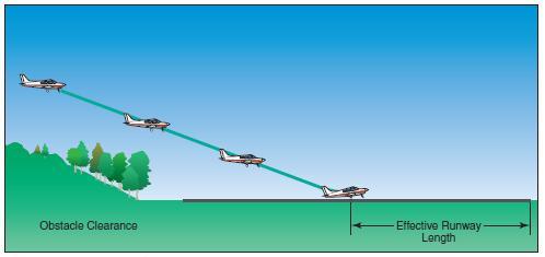
[Figures 8-20 Landing over an obstacle]
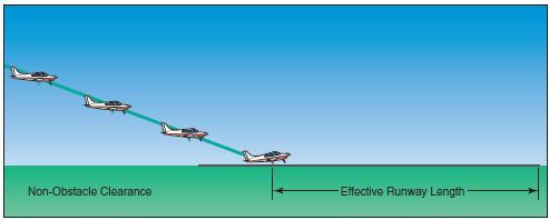
[Figure 8-21 Landing on a short-field]
As in short-field takeoffs, it is one of the most critical of the maximum performance operations. It requires that the pilot fly the airplane at one of its crucial performance capabilities while close to the ground in order to safely land within confined areas. This low-speed type of power-on approach is closely related to the performance of flight at minimum controllable airspeeds.
To land within a short-field or a confined area, the pilot must have precise, positive control of the rate of descent and airspeed to produce an approach that will clear any obstacles, result in little or no floating during the roundout, and permit the airplane to be stopped in the shortest possible distance. The procedures for landing in a short-field or for landing approaches over obstacles, as recommended in the AFM/POH, should be used. A stabilized approach is essential.
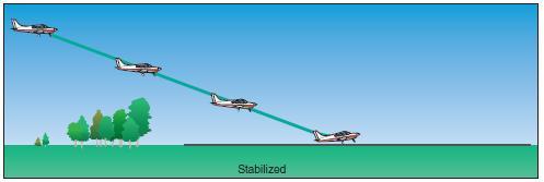
[Figures 8-22 Stabilized approach]
These procedures generally involve the use of full flaps, and the final approach started from an altitude of at least 500 feet higher than the touchdown area. A wider than normal pattern should be used so that the airplane can be properly configured and trimmed. In the absence of the manufacturer’s recommended approach speed, a speed of not more than 1.3 VSO should be used. For example, in an airplane that stalls at 60 knots with power off, and flaps and landing gear extended, the approach speed should not be higher than 78 knots. In gusty air, no more than one-half the gust factor should be added. An excessive amount of airspeed could result in a touchdown too far from the runway threshold or an after-landing roll that exceeds the available landing area. After the landing gear and full flaps have been extended, the pilot should simultaneously adjust the power and the pitch attitude to establish and maintain the proper descent angle and airspeed. A coordinated combination of both pitch and power adjustments is required. When this is done properly, very little change in the airplane’s pitch attitude and power setting is necessary to make corrections in the angle of descent and airspeed. The short-field approach and landing is in reality an accuracy approach to a spot landing. The procedures previously outlined in the section on the stabilized approach concept should be used. If it appears that the obstacle clearance is excessive and touchdown will occur well beyond the desired spot, leaving insufficient room to stop, power may be reduced while lowering the pitch attitude to steepen the descent path and increase the rate of descent. If it appears that the descent angle will not ensure safe clearance of obstacles, power should be increased while simultaneously raising the pitch attitude to shallow the descent path and decrease the rate of descent. Care must be taken to avoid an excessively low airspeed. If the speed is allowed to become too slow, an increase in pitch and application of full power Non-Obstacle Clearance Effective Runway Length Figure 8-21. Landing on a short-field. Figure 8-22. Stabilized approach. 8-18 Stabilized may only result in a further rate of descent. This occurs when the angle of attack is so great and creating so much drag that the maximum available power is insufficient to overcome it. This is generally referred to as operating in the region of reversed command or operating on the back side of the power curve. Because the final approach over obstacles is made at a relatively steep approach angle and close to the airplane’s stalling speed, the initiation of the roundout or flare must be judged accurately to avoid flying into the ground, or stalling prematurely and sinking rapidly. A lack of floating during the flare, with sufficient control to touch down properly, is one verification that the approach speed was correct. Touchdown should occur at the minimum controllable airspeed with the airplane in approximately the pitch attitude that will result in a power-off stall when the throttle is closed. Care must be exercised to avoid closing the throttle too rapidly before the pilot is ready for touchdown, as closing the throttle may result in an immediate increase in the rate of descent and a hard landing. Upon touchdown, the airplane should be held in this positive pitch attitude as long as the elevators remain effective. This will provide aerodynamic braking to assist in deceleration. Immediately upon touchdown, and closing the throttle, appropriate braking should be applied to minimize the after-landing roll. The airplane should be stopped within the shortest possible distance consistent with safety and controllability. If the proper approach speed has been maintained, resulting in minimum float during the roundout, and the touchdown made at minimum control speed, minimum braking will be required. Common errors in the performance of short-field approaches and landings are:
• Failure to allow enough room on final to set up the approach, necessitating an overly steep approach and high sink rate.
• Unstabilized approach.
• Undue delay in initiating glidepath corrections.
• Too low an airspeed on final resulting in inability to flare properly and landing hard.
• Too high an airspeed resulting in floating on roundout.
• Prematurely reducing power to idle on roundout resulting in hard landing.
• Touchdown with excessive airspeed.
• Excessive and/or unnecessary braking after touchdown.
• Failure to maintain directional control.
SOFT-FIELD APPROACH AND LANDING
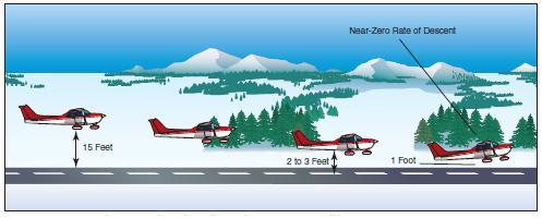
Landing on fields that are rough or have soft surfaces, such as snow, sand, mud, or tall grass requires unique procedures. When landing on such surfaces, the objective is to touch down as smoothly as possible, and at the slowest possible landing speed. The pilot must control the airplane in a manner that the wings support the weight of the airplane as long as practical, to minimize drag and stresses imposed on the landing gear by the rough or soft surface.
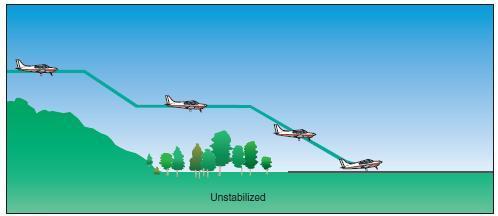 [Figures 8-23 Unstabilized approach]
The approach for the soft-field landing is similar to the normal approach used for operating into long, firm landing areas. The major difference between the two is that, during the soft-field landing, the airplane is held 1 to 2 feet off the surface in ground effect as long as possible. This permits a more gradual dissipation of forward speed to allow the wheels to touch down gently at minimum speed. This technique minimizes the nose-over forces that suddenly affect the airplane at the moment of touchdown. Power can be used throughout the level-off and touchdown to ensure touchdown at the slowest possible airspeed, and the airplane should be flown onto the ground with the weight fully supported by the wings.
[Figure 8-24. Soft/rough field approach and landing ]
The use of flaps during soft-field landings will aid in touching down at minimum speed and is recommended whenever practical. In low-wing airplanes, the flaps may suffer damage from mud, stones, or slush thrown up by the wheels. If flaps are used, it is generally inadvisable to retract them during the after-landing roll because the need for flap retraction is usually less important than the need for total concentration on maintaining full control of the airplane.
The final approach airspeed used for short-field landings is equally appropriate to soft-field landings. The use of higher approach speeds may result in excessive float in ground effect, and floating makes a smooth, controlled touchdown even more difficult. There is, however, no reason for a steep angle of descent unless obstacles are present in the approach path.
Touchdown on a soft or rough field should be made at the lowest possible airspeed with the airplane in a nose-high pitch attitude. In nosewheel-type airplanes, after the main wheels touch the surface, the pilot should hold sufficient back-elevator pressure to keep the nosewheel off the surface. Using back-elevator pressure and engine power, the pilot can control the rate at which the weight of the airplane is transferred from the wings to the wheels.
Field conditions may warrant that the pilot maintain a flight condition in which the main wheels are just touching the surface but the weight of the airplane is still being supported by the wings, until a suitable taxi surface is reached. At any time during this transition phase, before the weight of the airplane is being supported by the wheels, and before the nosewheel is on the surface, the pilot should be able to apply full power and perform a safe takeoff (obstacle clearance and field length permitting) should the pilot elect to abandon the landing. Once committed to a landing, the pilot should gently lower the nosewheel to the surface. A slight addition of power usually will aid in easing the nosewheel down.
The use of brakes on a soft field is not needed and should be avoided as this may tend to impose a heavy load on the nose gear due to premature or hard contact with the landing surface, causing the nosewheel to dig in. The soft or rough surface itself will provide sufficient reduction in the airplane’s forward speed. Often it will be found that upon landing on a very soft field, the pilot will need to increase power to keep the airplane moving and from becoming stuck in the soft surface.
Common errors in the performance of soft-field approaches and landings are:
• Excessive descent rate on final approach.
• Excessive airspeed on final approach.
• Unstabilized approach.
• Roundout too high above the runway surface.
• Poor power management during roundout and touchdown.
• Hard touchdown.
• Inadequate control of the airplane weight transfer from wings to wheels after touchdown.
• Allowing the nosewheel to “fall” to the runway after touchdown rather than controlling its descent.
POWER-OFF ACCURACY APPROACHES
Power-off accuracy approaches are approaches and landings made by gliding with the engine idling, through a specific pattern to a touchdown beyond and within 200 feet of a designated line or mark on the runway. The objective is to instill in the pilot the judgment and procedures necessary for accurately flying the airplane, without power, to a safe landing.
The ability to estimate the distance an airplane will glide to a landing is the real basis of all power-off accuracy approaches and landings. This will largely determine the amount of maneuvering that may be done from a given altitude. In addition to the ability to estimate distance, it requires the ability to maintain the proper glide while maneuvering the airplane.
With experience and practice, altitudes up to approximately 1,000 feet can be estimated with fair accuracy, while above this level the accuracy in judgment of height above the ground decreases, since all features tend to merge. The best aid in perfecting the ability to judge height above this altitude is through the indications of the altimeter and associating them with the general appearance of the Earth.
The judgment of altitude in feet, hundreds of feet, or thousands of feet is not as important as the ability to estimate gliding angle and its resultant distance. The pilot who knows the normal glide angle of the airplane can estimate with reasonable accuracy, the approximate spot along a given ground path at which the airplane will land, regardless of altitude. The pilot, who also has the ability to accurately estimate altitude, can judge how much maneuvering is possible during the glide, which is important to the choice of landing areas in an actual emergency.
The objective of a good final approach is to descend at an angle that will permit the airplane to reach the desired landing area, and at an airspeed that will result in minimum floating just before touchdown. To accomplish this, it is essential that both the descent angle and the airspeed be accurately controlled.
Unlike a normal approach when the power setting is variable, on a power-off approach the power is fixed at the idle setting. Pitch attitude is adjusted to control the airspeed. This will also change the glide or descent angle. By lowering the nose to keep the approach airspeed constant, the descent angle will steepen. If the airspeed is too high, raise the nose, and when the airspeed is too low, lower the nose. If the pitch attitude is raised too high, the airplane will settle rapidly due to a slow airspeed and insufficient lift. For this reason, never try to stretch a glide to reach the desired landing spot.
Uniform approach patterns such as the 90°, 180°, or 360° power-off approaches are described further in this chapter. Practice in these approaches provides the pilot with a basis on which to develop judgment in gliding distance and in planning an approach.
The basic procedure in these approaches involves closing the throttle at a given altitude, and gliding to a key position. This position, like the pattern itself, must not be allowed to become the primary objective; it is merely a convenient point in the air from which the pilot can judge whether the glide will safely terminate at the desired spot. The selected key position should be one that is appropriate for the available altitude and the wind condition. From the key position, the pilot must constantly evaluate the situation.
It must be emphasized that, although accurate spot touchdowns are important, safe and properly executed approaches and landings are vital. The pilot must never sacrifice a good approach or landing just to land on the desired spot.
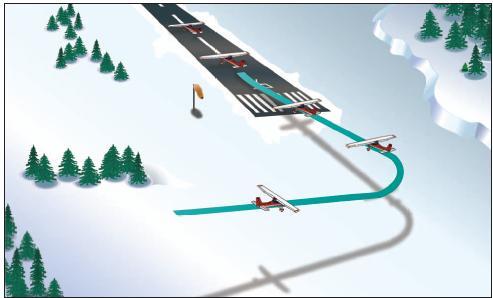
90° POWER-OFF APPROACH
The 90° power-off approach is made from a base leg and requires only a 90° turn onto the final approach. The approach path may be varied by positioning the base leg closer to or farther out from the approach end of the runway according to wind conditions.
[Figure 8-25 Plan the base leg for wind conditions]
The glide from the key position on the base leg through the 90° turn to the final approach is the final part of all accuracy landing maneuvers.
The 90° power-off approach usually begins
from a rectangular pattern at approximately 1,000 feet above the ground or at normal traffic pattern altitude. The airplane should be flown onto a downwind leg at the same distance from the landing surface as in a normal traffic pattern. The before landing checklist should be completed on the downwind leg, including extension of the landing gear if the airplane is equipped with retractable gear.
After a medium-banked turn onto the base leg is completed, the throttle should be retarded slightly and the airspeed allowed to decrease to the normal base-leg speed.

[Figure 8-26 90° power-off approach]
On the base leg, the airspeed, wind drift correction, and altitude should be maintained while proceeding to the 45° key position. At this position, the intended landing spot will appear to be on a 45° angle from the airplane’s nose.
The pilot can determine the strength and direction of the wind from the amount of crab necessary to hold the desired ground track on the base leg. This will help in planning the turn onto the final approach and in lowering the correct amount of flaps.
At the 45° key position, the throttle should be closed completely, the propeller control (if equipped) advanced to the full increase r.p.m. position, and altitude maintained until the airspeed decreases to the manufacturer’s recommended glide speed. In the absence of a recommended speed, use 1.4 VSO. When this airspeed is attained, the nose should be lowered to maintain the gliding speed and the controls retrimmed.
The base-to-final turn should be planned and accomplished so that upon rolling out of the turn the airplane will be aligned with the runway centerline. When on final approach, the wing flaps are lowered and the pitch attitude adjusted, as necessary, to establish the proper descent angle and airspeed (1.3 VSO), then the controls retrimmed. Slight adjustments in pitch attitude or flaps setting may be necessary to control the glide angle and airspeed. However, NEVER TRY TO STRETCH THE GLIDE OR RETRACT THE FLAPS to reach the desired landing spot. The final approach may be made with or without the use of slips.
After the final approach glide has been established, full attention is then given to making a good, safe landing rather than concentrating on the selected landing spot. The base-leg position and the flap setting already determined the probability of landing on the spot. In any event, it is better to execute a good landing 200 feet from the spot than to make a poor landing precisely on the spot.
180° POWER-OFF APPROACH
The 180° power-off approach is executed by gliding with the power off from a given point on a downwind leg to a preselected landing spot.

[Figure 8-27 180° power-off approach]
It is an extension of the principles involved in the 90° poweroff approach just described. Its objective is to further develop judgment in estimating distances and glide ratios, in that the airplane is flown without power from a higher altitude and through a 90° turn to reach the base-leg position at a proper altitude for executing the 90° approach.
The 180° power-off approach requires more planning and judgment than the 90° power-off approach. In the execution of 180° power-off approaches, the airplane is flown on a downwind heading parallel to the landing runway. The altitude from which this type of approach should be started will vary with the type of airplane, but it should usually not exceed 1,000 feet above the ground, except with large airplanes. Greater accuracy in judgment and maneuvering is required at higher altitudes.
When abreast of or opposite the desired landing spot, the throttle should be closed and altitude maintained while decelerating to the manufacturer’s recommended glide speed, or 1.4 VSO. The point at which the throttle is closed is the downwind key position.
The turn from the downwind leg to the base leg should be a uniform turn with a medium or slightly steeper bank. The degree of bank and amount of this initial turn will depend upon the glide angle of the airplane and the velocity of the wind. Again, the base leg should be positioned as needed for the altitude, or wind condition. Position the base leg to conserve or dissipate altitude so as to reach the desired landing spot.
The turn onto the base leg should be made at an altitude high enough and close enough to permit the airplane to glide to what would normally be the base key position in a 90° power-off approach.
Although the key position is important, it must not be overemphasized nor considered as a fixed point on the ground. Many inexperienced pilots may gain a conception of it as a particular landmark, such as a tree, crossroad, or other visual reference, to be reached at a certain altitude. This will result in a mechanical conception and leave the pilot at a total loss any time such objects are not present. Both altitude and geographical location should be varied as much as is practical to eliminate any such conception. After reaching the base key position, the approach and landing are the same as in the 90° power-off approach.
360° POWER-OFF APPROACH
The 360° power-off approach is one in which the airplane glides through a 360° change of direction to the preselected landing spot. The entire pattern is designed to be circular, but the turn may be shallowed, steepened, or discontinued at any point to adjust the accuracy of the flightpath.
The 360° approach is started from a position over the approach end of the landing runway or slightly to the side of it, with the airplane headed in the proposed landing direction and the landing gear and flaps retracted.

[Figure 8-28 360° power-off approach]
It is usually initiated from approximately 2,000 feet or more above the ground—where the wind may vary significantly from that at lower altitudes. This must be taken into account when maneuvering the airplane to a point from which a 90° or 180° power-off approach can be completed.
After the throttle is closed over the intended point of landing, the proper glide speed should immediately be established, and a medium-banked turn made in the desired direction so as to arrive at the downwind key position opposite the intended landing spot. At or just beyond the downwind key position, the landing gear may be extended if the airplane is equipped with retractable gear. The altitude at the downwind key position should be approximately 1,000 to 1,200 feet above the ground.
After reaching that point, the turn should be continued to arrive at a base-leg key position, at an altitude of about 800 feet above the terrain. Flaps may be used at this position, as necessary, but full flaps should not be used until established on the final approach. The angle of bank can be varied as needed throughout the pattern to correct for wind conditions and to align the airplane with the final approach. The turn-to-final should be completed at a minimum altitude of 300 feet above the terrain.
Common errors in the performance of power-off accuracy approaches are: • Downwind leg too far from the runway/landing area.
• Overextension of downwind leg resulting from tailwind.
• Inadequate compensation for wind drift on base leg.
• Skidding turns in an effort to increase gliding distance. Figure 8-28. 360° power-off approach.
• Failure to lower landing gear in retractable gear airplanes. • Attempting to “stretch” the glide during undershoot.
• Premature flap extension/landing gear extension.
• Use of throttle to increase the glide instead of merely clearing the engine
• Forcing the airplane onto the runway in order to avoid overshooting the designated landing spot.
EMERGENCY APPROACHES AND LANDINGS (SIMULATED)
From time to time on dual flights, the instructor should give simulated emergency landings by retarding the throttle and calling “simulated emergency landing.” The objective of these simulated emergency landings is to develop the pilot’s accuracy, judgment, planning, procedures, and confidence when little or no power is available.
A simulated emergency landing may be given with the airplane in any configuration. When the instructor calls “simulated emergency landing,” the pilot should immediately establish a glide attitude and ensure that the flaps and landing gear are in the proper configuration for the existing situation. When the proper glide speed is attained, the nose should then be lowered and the airplane trimmed to maintain that speed.
A constant gliding speed should be maintained because variations of gliding speed nullify all attempts at accuracy in judgment of gliding distance and the landing spot. The many variables, such as altitude, obstruction, wind direction, landing direction, landing surface and gradient, and landing distance requirements of the airplane will determine the pattern and approach procedures to use.
Utilizing any combination of normal gliding maneuvers, from wings level to spirals, the pilot should eventually arrive at the normal key position at a normal traffic pattern altitude for the selected landing area. From this point on, the approach will be as nearly as possible a normal power-off approach.
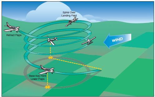
[Figure 8-29 Remain over intended landing area]
With the greater choice of fields afforded by higher altitudes, the inexperienced pilot may be inclined to delay making a decision, and with considerable altitude in which to maneuver, errors in maneuvering and estimation of glide distance may develop.
All pilots should learn to determine the wind direction and estimate its speed from the windsock at the airport, smoke from factories or houses, dust, brush fires, and windmills.
Once a field has been selected, the student pilot should always be required to indicate it to the instructor. Normally, the student should be required to plan and fly a pattern for landing on the field first elected until the instructor terminates the simulated emergencylanding. This will give the instructor an opportunity to explain and correct any errors; it will also give the student an opportunity to see the results of the errors. However, if the student realizes during the approach that a poor field has been selected—one that would obviously result in disaster if a landing were to be made—and there is a more advantageous field within gliding distance, a change to the better field should be permitted. The hazards involved in these last-minute decisions, such as excessive maneuvering at very low altitudes, should be thoroughly explained by the instructor.
Slipping the airplane, using flaps, varying the position of the base leg, and varying the turn onto final approach should be stressed as ways of correcting for misjudgment of altitude and glide angle.
Eagerness to get down is one of the most common faults of inexperienced pilots during simulated emergency landings. In giving way to this, they forget about speed and arrive at the edge of the field with too much speed to permit a safe landing. Too much speed may be just as dangerous as too little; it results in excessive floating and overshooting the desired landing spot. It should be impressed on the students that they cannot dive at a field and expect to land on it.
During all simulated emergency landings, the engine should be kept warm and cleared. During a simulated emergency landing, either the instructor or the student should have complete control of the throttle. There should be no doubt as to who has control since many near accidents have occurred from such misunderstandings. Every simulated emergency landing approach should be terminated as soon as it can be determined whether a safe landing could have been made. In no case should it be continued to a point where it creates an undue hazard or an annoyance to persons or property on the ground.
In addition to flying the airplane from the point of simulated engine failure to where a reasonable safe landing could be made, the student should also be taught certain emergency cockpit procedures. The habit of performing these cockpit procedures should be developed to such an extent that, when an engine failure actually occurs, the student will check the critical items that would be necessary to get the engine operating again while selecting a field and planning an approach. Combining the two operations— accomplishing emergency procedures and planning
Figure 8-30. Sample emergency checklist. and flying the approach—will be difficult for the student during the early training in emergency landings. There are definite steps and procedures to be followed in a simulated emergency landing. Although they may differ somewhat from the procedures used in an actual emergency, they should be learned thoroughly by the student, and each step called out to the instructor. The use of a checklist is strongly recommended. Most airplane manufacturers provide a checklist of the appropriate items.
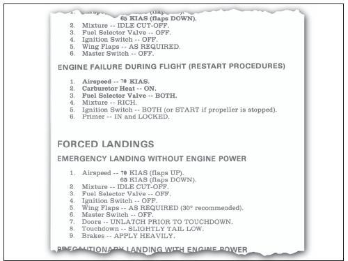
[Figure 8-30 Sample emergency checklist]
Critical items to be checked should include the position of the fuel tank selector, the quantity of fuel in the tank selected, the fuel pressure gauge to see if the electric fuel pump is needed, the position of the mixture control, the position of the magneto switch, and the use of carburetor heat. Many actual emergency landings have been made and later found to be the result of the fuel selector valve being positioned to an empty tank while the other tank had plenty of fuel. It may be wise to change the position of the fuel selector valve even though the fuel gauge indicates fuel in all tanks because fuel gauges can be inaccurate. Many actual emergency landings could have been prevented if the pilots had developed the habit of checking these critical items during flight training to the extent that it carried over into later flying.
Instruction in emergency procedures should not be limited to simulated emergency landings caused by power failures. Other emergencies associated with the operation of the airplane should be explained, demonstrated, and practiced if practicable. Among these emergencies are such occurrences as fire in flight, electrical or hydraulic system malfunctions, unexpected severe weather conditions, engine overheating, imminent fuel exhaustion, and the emergency operation of airplane systems and equipment.
FAULTY APPROACHES AND LANDINGS
LOW FINAL APPROACH
When the base leg is too low, insufficient power is used, landing flaps are extended prematurely, or the velocity of the wind is misjudged, sufficient altitude may be lost, which will cause the airplane to be well below the proper final approach path. In such a situation, the pilot would have to apply considerable power to fly the airplane (at an excessively low altitude) up to the runway threshold. When it is realized the runway will not be reached unless appropriate action is taken, power must be applied immediately to maintain the airspeed while the pitch attitude is raised to increase lift and stop the descent. When the proper approach path has been intercepted, the correct approach attitude should be reestablished and the power reduced and a stabilized approach maintained.
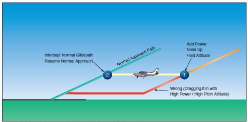 [Figure 8-31 Right and wrong methods of correction for low final approach]
DO NOT increase the pitch attitude without increasing the power, since the airplane will decelerate rapidly and may approach the critical angle of attack and stall. DO NOT retract the flaps; this will suddenly decrease lift and cause the airplane to sink more rapidly. If there is any doubt about the approach being safely completed, it is advisable to EXECUTE AN IMMEDIATE GO-AROUND.
HIGH FINAL APPROACH
When the final approach is too high, lower the flaps as required. Further reduction in power may be necessary, while lowering the nose simultaneously to maintain approach airspeed and steepen the approach path.
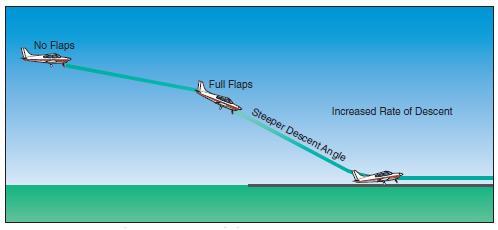
[Figure 8-32 Change in glidepath and increase in descent rate for high final approach]
When the proper approach path has been intercepted, adjust the power as required to maintain a stabilized approach. When steepening the approach path, however, care must be taken that the descent does not result in an excessively high sink rate. If a high sink rate is continued close to the surface, it may be difficult to slow to a proper rate prior to ground contact. Any sink rate in excess of 800 - 1,000 feet per minute is considered excessive. A go-around should be initiated if the sink rate becomes excessive.
SLOW FINAL APPROACH
When the airplane is flown at a slower-than-normal airspeed on the final approach, the pilot’s judgment of the rate of sink (descent) and the height of roundout will be difficult. During an excessively slow approach, the wing is operating near the critical angle of attack and, depending on the pitch attitude changes and control usage, the airplane may stall or sink rapidly, contacting the ground with a hard impact. Whenever a slow-speed approach is noted, the pilot should apply power to accelerate the airplane and increase the lift to reduce the sink rate and to prevent a stall. This should be done while still at a high enough altitude to reestablish the correct approach airspeed and attitude. If too slow and too low, it is best to EXECUTE A GO-AROUND.
USE OF POWER
Power can be used effectively during the approach and roundout to compensate for errors in judgment. Power can be added to accelerate the airplane to increase lift without increasing the angle of attack; thus, the descent can be slowed to an acceptable rate. If the proper landing attitude has been attained and the airplane is only slightly high, the landing attitude should be held constant and sufficient power applied to help ease the airplane onto the ground. After the airplane has touched down, it will be necessary to close the throttle so the additional thrust and lift will be removed and the airplane will stay on the ground.
HIGH ROUNDOUT
Sometimes when the airplane appears to temporarily stop moving downward, the roundout has been made too rapidly and the airplane is flying level, too high above the runway. Continuing the roundout would further reduce the airspeed, resulting in an increase in angle of attack to the critical angle. This would result in the airplane stalling and dropping hard onto the runway. To prevent this, the pitch attitude should be held constant until the airplane decelerates enough to again start descending. Then the roundout can be continued to establish the proper landing attitude. This procedure should only be used when there is adequate airspeed. It may be necessary to add a slight amount of power to keep the airspeed from decreasing excessively and to avoid losing lift too rapidly.
Although back-elevator pressure may be relaxed slightly, the nose should not be lowered any perceptible amount to make the airplane descend when fairly close to the runway unless some power is added momentarily. The momentary decrease in lift that would result from lowering the nose and decreasing the angle of attack may be so great that the airplane might contact the ground with the nosewheel first, which could collapse.
When the proper landing attitude is attained, the airplane is approaching a stall because the airspeed is decreasing and the critical angle of attack is being approached, even though the pitch attitude is no longer being increased.
[Figure 8-33 Rounding out too high]
It is recommended that a GO-AROUND be executed any time it appears the nose must be lowered significantly or that the landing is in any other way uncertain.
LATE OR RAPID ROUNDOUT
Starting the roundout too late or pulling the elevator control back too rapidly to prevent the airplane from touching down prematurely can impose a heavy load factor on the wing and cause an accelerated stall.
Suddenly increasing the angle of attack and stalling the airplane during a roundout is a dangerous situation since it may cause the airplane to land extremely hard on the main landing gear, and then bounce back into the air. As the airplane contacts the ground, the tail will be forced down very rapidly by the back-elevator pressure and by inertia acting downward on the tail.
Recovery from this situation requires prompt and positive application of power prior to occurrence of the stall. This may be followed by a normal landing if sufficient runway is available—otherwise the pilot should EXECUTE A GO-AROUND immediately.
If the roundout is late, the nosewheel may strike the runway first, causing the nose to bounce upward. No attempt should be made to force the airplane back onto the ground; a GO-AROUND should be executed immediately.
FLOATING DURING ROUNDOUT
If the airspeed on final approach is excessive, it will usually result in the airplane floating.
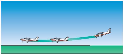
[Figure 8-34 Floating during roundout]
Before touchdown can be made, the airplane may be well past the desired landing point and the available runway may be insufficient. When diving an airplane on final approach to land at the proper point, there will be an appreciable increase in airspeed. The proper touchdown attitude cannot be established without producing an excessive angle of attack and lift. This will cause the airplane to gain altitude or balloon.
Any time the airplane floats, judgment of speed, height, and rate of sink must be especially acute. The pilot must smoothly and gradually adjust the pitch attitude as the airplane decelerates to touchdown speed and starts to settle, so the proper landing attitude is attained at the moment of touchdown. The slightest either ballooning or bouncing.
The recovery from floating will depend on the amount of floating and the effect of any crosswind, as well as the amount of runway remaining. Since prolonged floating utilizes considerable runway length, it should be avoided especially on short runways or in strong crosswinds. If a landing cannot be made on the first third of the runway, or the airplane drifts sideways, the pilot should EXECUTE A GO-AROUND.
BALLOONING DURING ROUNDOUT
If the pilot misjudges the rate of sink during a landing and thinks the airplane is descending faster than it should, there is a tendency to increase the pitch attitude and angle of attack too rapidly. This not only stops the descent, but actually starts the airplane climbing. This climbing during the roundout is known as ballooning.
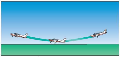
[Figure 8-35 Ballooning during roundout]
Ballooning can be dangerous because the height above the ground is increasing and the airplane may be rapidly approaching a stalled condition. The altitude gained in each instance will depend on the airspeed or the speed with which the pitch attitude is increased.
When ballooning is slight, a constant landing attitude should be held and the airplane allowed to gradually decelerate and settle onto the runway. Depending on the severity of ballooning, the use of throttle may be helpful in cushioning the landing. By adding power, thrust can be increased to keep the airspeed from decelerating too rapidly and the wings from suddenly losing lift, but throttle must be closed immediately after touchdown. Remember that torque will be created as power is applied; therefore, it will be necessary to use rudder pressure to keep the airplane straight as it settles onto the runway.
When ballooning is excessive, it is best to EXECUTE A GO-AROUND IMMEDIATELY; DO NOT ATTEMPT TO SALVAGE THE LANDING. Power must be applied before the airplane enters a stalled condition. The pilot must be extremely cautious of ballooning when there is a crosswind present because the crosswind correction may be inadvertently released or it may become inadequate. Because of the lower airspeed after ballooning, the crosswind affects the airplane more. Consequently, the wing will have to be lowered even further to compensate for the increased drift. It is imperative that the pilot makes certain that the appropriate wing is down and that directional control is maintained with opposite rudder. If there is any doubt, or the airplane starts to drift, EXECUTE A GO-AROUND.
BOUNCING DURING TOUCHDOWN
When the airplane contacts the ground with a sharp impact as the result of an improper attitude or an excessive rate of sink, it tends to bounce back into the air. Though the airplane’s tires and shock struts provide some springing action, the airplane does not bounce like a rubber ball. Instead, it rebounds into the air because the wing’s angle of attack was abruptly increased, producing a sudden addition of lift.
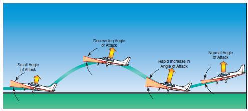
[Figure 8-36 Bouncing during touchdown]
The abrupt change in angle of attack is the result of inertia instantly forcing the airplane’s tail downward when the main wheels contact the ground sharply. The severity of the bounce depends on the airspeed at the moment of contact and the degree to which the angle of attack or pitch attitude was increased. Since a bounce occurs when the airplane makes contact with the ground before the proper touchdown attitude is attained, it is almost invariably accompanied by the application of excessive back-elevator pressure. This is usually the result of the pilot realizing too late that the airplane is not in the proper attitude and attempting to establish it just as the second touchdown occurs.
The corrective action for a bounce is the same as for ballooning and similarly depends on its severity. When it is very slight and there is no extreme change in the airplane’s pitch attitude, a follow-up landing may be executed by applying sufficient power to cushion the subsequent touchdown, and smoothly adjusting the pitch to the proper touchdown attitude.
In the event a very slight bounce is encountered while landing with a crosswind, crosswind correction must be maintained while the next touchdown is made. Remember that since the subsequent touchdown will be made at a slower airspeed, the upwind wing will have to be lowered even further to compensate for drift.
Extreme caution and alertness must be exercised any time a bounce occurs, but particularly when there is a crosswind. Inexperienced pilots will almost invariably release the crosswind correction. When one main wheel of the airplane strikes the runway, the other wheel will touch down immediately afterwards, and the wings will become level. Then, with no crosswind correction as the airplane bounces, the wind will cause the airplane to roll with the wind, thus exposing even more surface to the crosswind and drifting the airplane more rapidly.
When a bounce is severe, the safest procedure is to EXECUTE A GO-AROUND IMMEDIATELY. No attempt to salvage the landing should be made. Full power should be applied while simultaneously maintaining directional control, and lowering the nose to a safe climb attitude. The go-around procedure should be continued even though the airplane may descend and another bounce may be encountered. It would be extremely foolish to attempt a landing from a bad bounce since airspeed diminishes very rapidly in the nose-high attitude, and a stall may occur before a subsequent touchdown could be made.
PORPOISING
In a bounced landing that is improperly recovered, the airplane comes in nose first setting off a series of motions that imitate the jumps and dives of a porpoise— hence the name.
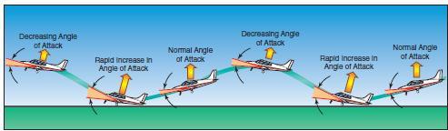
[Figure 8-37 Porpoising]
The problem is improper airplane attitude at touchdown, sometimes caused by inattention, not knowing where the ground is, mistrimming or forcing the airplane onto the runway.
Ground effect decreases elevator control effectiveness and increases the effort required to raise the nose. Not enough elevator or stabilator trim can result in a noselow contact with the runway and a porpoise develops.
Porpoising can also be caused by improper airspeed control. Usually, if an approach is too fast, the airplane floats and the pilot tries to force it on the runway when the airplane still wants to fly. Agust of wind, a bump in the runway, or even a slight tug on the control wheel will send the airplane aloft again.
The corrective action for a porpoise is the same as for a bounce and similarly depends on its severity. When it is very slight and there is no extreme change in the airplane’s pitch attitude, a follow-up landing may be executed by applying sufficient power to cushion the subsequent touchdown, and smoothly adjusting the pitch to the proper touchdown attitude.
When a porpoise is severe, the safest procedure is to EXECUTE A GO-AROUND IMMEDIATELY. In a severe porpoise, the airplane’s pitch oscillations can become progressively worse, until the airplane strikes the runway nose first with sufficient force to collapse the nose gear. Pilot attempts to correct a severe porpoise with flight control and power inputs will most likely be untimely and out of sequence with the oscillations, and only make the situation worse. No attempt to salvage the landing should be made. Full power should be applied while simultaneously maintaining directional control, and lowering the nose to a safe climb attitude.
WHEELBARROWING
When a pilot permits the airplane weight to become concentrated about the nosewheel during the takeoff or landing roll, a condition known as wheelbarrowing will occur. Wheelbarrowing may cause loss of directional control during the landing roll because braking action is ineffective, and the airplane tends to swerve or pivot on the nosewheel, particularly in crosswind conditions. One of the most common causes of wheelbarrowing during the landing roll is a simultaneous touchdown of the main and nosewheel, with excessive speed, followed by application of forward pressure on the elevator control. Usually, the situation can be corrected by smoothly applying back-elevator pressure. However, if wheelbarrowing is encountered and runway and other conditions permit, it may be advisable to promptly initiate a go-around. Wheelbarrowing will not occur if the pilot achieves and maintains the correct landing attitude, touches down at the proper speed, and gently lowers the nosewheel while losing speed on rollout. If the pilot decides to stay on the ground rather than attempt a go-around or if directional control is lost, the throttle should be closed and the pitch attitude smoothly but firmly rotated to the proper landing attitude. Raise the flaps to reduce lift and to increase the load on the main wheels for better braking action.
HARD LANDING
When the airplane contacts the ground during landings, its vertical speed is instantly reduced to zero. Unless provisions are made to slow this vertical speed and cushion the impact of touchdown, the force of contact with the ground may be so great it could cause structural damage to the airplane.
The purpose of pneumatic tires, shock absorbing landing gears, and other devices is to cushion the impact and to increase the time in which the airplane’s vertical descent is stopped. The importance of this cushion may be understood from the computation that a 6-inch free fall on landing is roughly equal, to a 340-foot-per-minute descent. Within a fraction of a second, the airplane must be slowed from this rate of vertical descent to zero, without damage.
During this time, the landing gear together with some aid from the lift of the wings must supply whatever force is needed to counteract the force of the airplane’s inertia and weight. The lift decreases rapidly as the airplane’s forward speed is decreased, and the force on the landing gear increases by the impact of touchdown. When the descent stops, the lift will be practically zero, leaving the landing gear alone to carry both the airplane’s weight and inertia force. The load imposed at the instant of touchdown may easily be three or four times the actual weight of the airplane depending on the severity of contact.
TOUCHDOWN IN A DRIFT OR CRAB
At times the pilot may correct for wind drift by crabbing on the final approach. If the roundout and touchdown are made while the airplane is drifting or in a crab, it will contact the ground while moving sideways. This will impose extreme side loads on the landing gear, and if severe enough, may cause structural failure.
The most effective method to prevent drift in primary training airplanes is the wing-low method. This technique keeps the longitudinal axis of the airplane aligned with both the runway and the direction of motion throughout the approach and touchdown.
There are three factors that will cause the longitudinal axis and the direction of motion to be misaligned during touchdown: drifting, crabbing, or a combination of both.
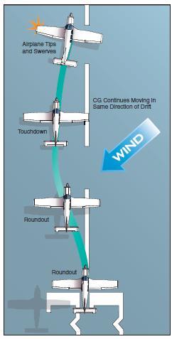
[Figure 8-38. Drifting during touchdown.]
If the pilot has not taken adequate corrective action to avoid drift during a crosswind landing, the main wheels’ tire tread offers resistance to the airplane’s sideward movement in respect to the ground. Consequently, any sidewise velocity of the airplane is abruptly decelerated, with the result that the inertia force is as shown in figure 8-38. This creates a moment around the main wheel when it contacts the ground, tending to overturn or tip the airplane. If the windward wingtip is raised by the action of this moment, all the weight and shock of landing will be borne by one main wheel. This could cause structural damage.
Not only are the same factors present that are attempting to raise a wing, but the crosswind is also acting on the fuselage surface behind the main wheels, tending to yaw (weathervane) the airplane into the wind. This often results in a ground loop.
GROUND LOOP
A ground loop is an uncontrolled turn during ground operation that may occur while taxiing or taking off, but especially during the after-landing roll. Drift or weathervaning does not always cause a ground loop, although these things may cause the initial swerve. Careless use of the rudder, an uneven ground surface, or a soft spot that retards one main wheel of the airplane may also cause a swerve. In any case, the initial swerve tends to make the airplane ground loop, whether it is a tailwheel-type or nosewheel-type.
[Figure 8-39 Start of a ground loop]
Nosewheel-type airplanes are somewhat less prone to ground loop than tailwheel-type airplanes. Since the center of gravity (CG) is located forward of the main landing gear on these airplanes, any time a swerve develops, centrifugal force acting on the CG will tend to stop the swerving action.
If the airplane touches down while drifting or in a crab, the pilot should apply aileron toward the high wing and stop the swerve with the rudder. Brakes should be used to correct for turns or swerves only when the rudder is inadequate. The pilot must exercise caution when applying corrective brake action because it is very easy to overcontrol and aggravate the situation. If brakes are used, sufficient brake should be applied on the low-wing wheel (outside of the turn) to stop the swerve. When the wings are approximately level, the new direction must be maintained until the airplane has slowed to taxi speed or has stopped.
In nosewheel airplanes, a ground loop is almost always a result of wheelbarrowing. The pilot must be aware that even though the nosewheel-type airplane is less prone than the tailwheel-type airplane, virtually every type of airplane, including large multiengine airplanes, can be made to ground loop when sufficiently mishandled.
WING RISING AFTER TOUCHDOWN
When landing in a crosswind, there may be instances when a wing will rise during the after-landing roll. This may occur whether or not there is a loss of directional Wind Force Center of Gravity Force Resisting Side Motion Inertia Force Weight Airplane Tips and Swerves CG Continues Moving in Same Direction of Drift Touchdown Roundout Roundout Figure 8-39. Start of a ground loop control, depending on the amount of crosswind and the degree of corrective action. Any time an airplane is rolling on the ground in a crosswind condition, the upwind wing is receiving a greater force from the wind than the downwind wing. This causes a lift differential. Also, as the upwind wing rises, there is an increase in the angle of attack, which increases lift on the upwind wing, rolling the airplane downwind.
When the effects of these two factors are great enough, the upwind wing may rise even though directional control is maintained. If no correction is applied, it is possible that the upwind wing will rise sufficiently to cause the downwind wing to strike the ground.
In the event a wing starts to rise during the landing roll, the pilot should immediately apply more aileron pressure toward the high wing and continue to maintain direction. The sooner the aileron control is applied, the more effective it will be. The further a wing is allowed to rise before taking corrective action, the more airplane surface is exposed to the force of the crosswind. This diminishes the effectiveness of the aileron.
HYDROPLANING
Hydroplaning is a condition that can exist when an airplane is landed on a runway surface contaminated with standing water, slush, and/or wet snow. Hydroplaning can have serious adverse effects on ground controllability and braking efficiency. The three basic types of hydroplaning are dynamic hydroplaning, reverted rubber hydroplaning, and viscous hydroplaning. Any one of the three can render an airplane partially or totally uncontrollable anytime during the landing roll.
DYNAMIC HYDROPLANING
Dynamic hydroplaning is a relatively high-speed phenomenon that occurs when there is a film of water on the runway that is at least one-tenth inch deep. As the speed of the airplane and the depth of the water increase, the water layer builds up an increasing resistance to displacement, resulting in the formation of a wedge of water beneath the tire. At some speed, termed the hydroplaning speed (VP), the water pressure equals the weight of the airplane and the tire is lifted off the runway surface. In this condition, the tires no longer contribute to directional control and braking action is nil.
Dynamic hydroplaning is related to tire inflation pressure. Data obtained during hydroplaning tests have shown the minimum dynamic hydroplaning speed (VP) of a tire to be 8.6 times the square root of the tire pressure in pounds per square inch (PSI). For an airplane with a main tire pressure of 24 pounds, the calculated hydroplaning speed would be approximately 42 knots. It is important to note that the calculated speed referred to above is for the start of dynamic hydroplaning. Once hydroplaning has started, it may persist to a significantly slower speed depending on the type being experienced.
REVERTED RUBBER HYDROPLANING
Reverted rubber (steam) hydroplaning occurs during heavy braking that results in a prolonged locked-wheel skid. Only a thin film of water on the runway is required to facilitate this type of hydroplaning.
The tire skidding generates enough heat to cause the rubber in contact with the runway to revert to its original uncured state. The reverted rubber acts as a seal between the tire and the runway, and delays water exit from the tire footprint area. The water heats and is converted to steam which supports the tire off the runway.
Reverted rubber hydroplaning frequently follows an encounter with dynamic hydroplaning, during which time the pilot may have the brakes locked in an attempt to slow the airplane. Eventually the airplane slows enough to where the tires make contact with the runway surface and the airplane begins to skid. The remedy for this type of hydroplane is for the pilot to release the brakes and allow the wheels to spin up and apply moderate braking. Reverted rubber hydroplaning is insidious in that the pilot may not know when it begins, and it can persist to very slow groundspeeds (20 knots or less).
VISCOUS HYDROPLANING
Viscous hydroplaning is due to the viscous properties of water. A thin film of fluid no more than one thousandth of an inch in depth is all that is needed. The tire cannot penetrate the fluid and the tire rolls on top of the film. This can occur at a much lower speed than dynamic hydroplane, but requires a smooth or smooth acting surface such as asphalt or a touchdown area coated with the accumulated rubber of past landings. Such a surface can have the same friction coefficient as wet ice.
When confronted with the possibility of hydroplaning, it is best to land on a grooved runway (if available). Touchdown speed should be as slow as possible consistent with safety. After the nosewheel is lowered to the runway, moderate braking should be applied. If deceleration is not detected and hydroplaning is suspected, the nose should be raised and aerodynamic drag utilized to decelerate to a point where the brakes do become effective.
Proper braking technique is essential. The brakes should be applied firmly until reaching a point just short of a skid. At the first sign of a skid, the pilot should release brake pressure and allow the wheels to spin up. Directional control should be maintained as far as possible with the rudder. Remember that in a crosswind, if hydroplaning should occur, the crosswind will cause the airplane to simultaneously weathervane into the wind as well as slide downwind.