Airplane Ground Schools
Knowledge of Flying is Our passion.
Serving the General Aviation Community
PRIMARY FLIGHT CONTROLS
Airplane control systems are carefully designed to provide a natural feel, and at the same time, allow adequate responsiveness to control inputs. At low airspeeds, the controls usually feel soft and sluggish, and the airplane responds slowly to control applications. At high speeds, the controls feel firm and the response is more rapid.
Movement of any of the three primary flight control surfaces changes the airflow and pressure distribution over and around the airfoil. These changes affect the lift and drag produced by the airfoil/control surface combination, and allow a pilot to control the airplane about its three axes of rotation.
Design features limit the amount of deflection of flight control surfaces. For example, control-stop mechanisms may be incorporated into the flight controls, or movement of the control column and/or rudder pedals may be limited. The purpose of these design limits is to prevent the pilot from inadvertently overcontrolling and overstressing the aircraft during normal maneuvers.
A properly designed airplane should be stable and easily controlled during maneuvering. Control surface inputs cause movement about the three axes of rotation. The types of stability an airplane exhibits also relate to the three axes of rotation.
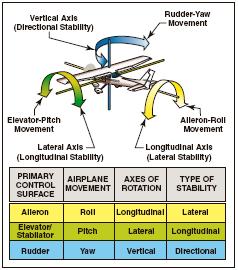
[Figure 4-1. Airplane controls, movement, axes of rotation, and type of stability.]
AILERONS
Ailerons control roll about the longitudinal axis. The ailerons are attached to the outboard trailing edge of each wing and move in the opposite direction from each other. Ailerons are connected by cables, bellcranks, pulleys or push-pull tubes to each other and to the control wheel.
Moving the control wheel to the right causes the right aileron to deflect upward and the left aileron to deflect downward. The upward deflection of the right aileron decreases the camber resulting in decreased lift on the right wing. The corresponding downward deflection of the left aileron increases the camber resulting in increased lift on the left wing. Thus, the increased lift on the left wing and the decreased lift on the right wing causes the airplane to roll to the right.
ADVERSE YAW
Since the downward deflected aileron produces more lift, it also produces more drag. This added drag attempts to yaw the airplane’s nose in the direction of the raised wing. This is called adverse yaw.
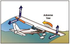
[Figure 4-2. Adverse yaw is caused by higher drag on the outside wing, which is producing more lift.]
The rudder is used to counteract adverse yaw, and the amount of rudder control required is greatest at low airspeeds, high angles of attack, and with large aileron deflections. However, with lower airspeeds, the vertical stabilizer/rudder combination becomes less effective, and magnifies the control problems associated with adverse yaw.
All turns are coordinated by use of ailerons, rudder, and elevator. Applying aileron pressure is necessary to place the airplane in the desired angle of bank, while simultaneously applying rudder pressure to counteract the resultant adverse yaw. During a turn, the angle of attack must be increased by applying elevator pressure because more lift is required than when in straight-andlevel flight. The steeper the turn, the more back elevator pressure is needed.
As the desired angle of bank is established, aileron and rudder pressures should be relaxed. This will stop the bank from increasing because the aileron and rudder control surfaces will be neutral in their streamlined position. Elevator pressure should be held constant to maintain a constant altitude.
The rollout from a turn is similar to the roll-in except the flight controls are applied in the opposite direction. Aileron and rudder are applied in the direction of the rollout or toward the high wing. As the angle of bank decreases, the elevator pressure should be relaxed as necessary to maintain altitude.
DIFFERENTIAL AILERONS
With differential ailerons, one aileron is raised a greater distance than the other aileron is lowered for a given movement of the control wheel. This produces an increase in drag on the descending wing. The greater drag results from deflecting the up aileron on the descending wing to a greater angle than the down aileron on the rising wing. While adverse yaw is reduced, it is not eliminated completely.
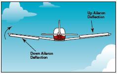
[Figure 4-3. Differential ailerons.]
FRISE-TYPE AILERONS
With a Frise-type aileron, when pressure is applied to the control wheel, the aileron that is being raised pivots on an offset hinge. This projects the leading edge of the aileron into the airflow and creates drag. This helps equalize the drag created by the lowered aileron on the opposite wing and reduces adverse yaw.
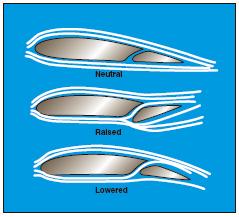
[Figure 4-4. Frise-type allerons]
The Frise-type aileron also forms a slot so that air flows smoothly over the lowered aileron, making it more effective at high angles of attack. Frise-type ailerons also may be designed to function differentially. Like the differential aileron, the Frise-type aileron does not eliminate adverse yaw entirely. Coordinated rudder application is still needed wherever ailerons are applied.
COUPLED AILERONS AND RUDDER
Coupled ailerons and rudder means these controls are linked. This is accomplished with rudder-aileron interconnect springs, which help correct for aileron drag by automatically deflecting the rudder at the same time the ailerons are deflected. For example, when the control yoke is moved to produce a left roll, the interconnect cable and spring pulls forward on the left rudder pedal just enough to prevent the nose of the airplane from yawing to the right. The force applied to the rudder by the springs can be overridden if it becomes necessary to slip the airplane.
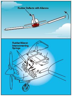
[Figure 4-5 Coupled ailerons and rudder.]
ELEVATOR
The elevator controls pitch about the lateral axis. Like the ailerons on small airplanes, the elevator is connected to the control column in the cockpit by a series of mechanical linkages. Aft movement of the control column deflects the trailing edge of the elevator surface up. This is usually referred to as up elevator.
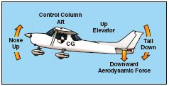
[Figure 4-6. The elevator is the primary control for changing the pitch attitude of an airplane.]
The up-elevator position decreases the camber of the elevator and creates a downward aerodynamic force, which is greater than the normal tail-down force that exists in straight-and-level flight. The overall effect causes the tail of the airplane to move down and the nose to pitch up. The pitching moment occurs about the center of gravity (CG). The strength of the pitching moment is determined by the distance between the CG and the horizontal tail surface, as well as by the aerodynamic effectiveness of the horizontal tail surface.
Moving the control column forward has the opposite effect. In this case, elevator camber increases, creating more lift (less tail-down force) on the horizontal stabilizer/elevator. This moves the tail upward and pitches the nose down. Again, the pitching moment occurs about the CG.
As mentioned earlier in the coverage on stability, power, thrustline, and the position of the horizontal tail surfaces on the empennage are factors in how effective the elevator is in controlling pitch. For example, the horizontal tail surfaces may be attached near the lower part of the vertical stabilizer, at the midpoint, or at the high point, as in the T-tail design.
T-TAIL
In a T-tail configuration, the elevator is above most of the effects of downwash from the propeller as well as airflow around the fuselage and/or wings during normal flight conditions. Operation of the elevators in this undisturbed air makes for control movements that are consistent throughout most flight regimes. T-tail designs have become popular on many light airplanes and on large aircraft, especially those with aft-fuselage mounted engines since the T-tail configuration removes the tail from the exhaust blast of the engines. Seaplanes and amphibians often have T-tails in order to keep the horizontal surfaces as far from the water as possible. An additional benefit is reduced vibration and noise inside the aircraft.
At slow speeds, the elevator on a T-tail aircraft must be moved through a larger number of degrees of travel to raise the nose a given amount as compared to a conventional-tail aircraft. This is because the conventional-tail aircraft has the downwash from the propeller pushing down on the tail to assist in raising the nose. Since controls on aircraft are rigged in such a manner as to require increasing control forces for increased control travel, the forces required to raise the nose of a T-tail aircraft are greater than for a conventional-tail aircraft. Longitudinal stability of a trimmed aircraft is the same for both types of configuration, but the pilot must be aware that at slow speeds during takeoffs and landings or stalls, the control forces will be greater than for similar size airplanes equipped with conventional tails.
T-tail airplanes also require additional design considerations to counter the problem of flutter. Since the weight of the horizontal surfaces is at the top of the vertical stabilizer, the moment arm created causes high loads on the vertical stabilizer which can result in flutter. Engineers must compensate for this by increasing the design stiffness of the vertical stabilizer, usually resulting in a weight penalty over conventional tail designs.
When flying at a very high angle of attack with a low airspeed and an aft CG, the T-tail airplane may be susceptible to a deep stall. In a deep stall, the airflow over the horizontal tail is blanketed by the disturbed airflow from the wings and fuselage. In these circumstances, elevator or stabilator control could be diminished, making it difficult to recover from the stall. It should be noted that an aft CG could be a contributing factor in these incidents since similar recovery problems are also found with conventional-tail aircraft with an aft CG.
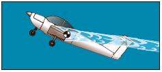
[Figure 4-7 Airplane with a T-tail design at a high angle of attack and an aft CG.]
Since flight at a high angle of attack with a low airspeed and an aft CG position can be dangerous, many airplanes have systems to compensate for this situation. The systems range from control stops to elevator down springs. An elevator down spring assists in lowering the nose to prevent a stall caused by the aft CG position. The stall occurs because the properly trimmed airplane is flying with the elevator in a trailing edge down position, forcing the tail up and the nose down. In this unstable condition, if the airplane encounters turbulence and slows down further, the trim tab no longer positions the elevator in the nose-down position. The elevator then streamlines, and the nose of the aircraft pitches upward. This aggravates the situation and can possibly result in a stall.
The elevator down spring produces a mechanical load on the elevator, causing it to move toward the nosedown position if not otherwise balanced. The elevator trim tab balances the elevator down spring to position the elevator in a trimmed position. When the trim tab becomes ineffective, the down spring drives the elevator to a nose down position. The nose of the aircraft lowers, speed builds up, and a stall is prevented.
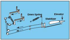
[Figure 4-8. When the aerodynamic efficiency of the horizontal tail surface is inadequate due to an aft center of gravity condition, an elevator down spring may be used to supply a mechanical load to lower the nose.]
The elevator must also have sufficient authority to hold the nose of the airplane up during the roundout for a landing. In this case, a forward CG may cause a problem. During the landing flare, power normally is reduced, which decreases the airflow over the empennage. This, coupled with the reduced landing speed, makes the elevator less effective.
From this discussion, it should be apparent that pilots must understand and follow proper loading procedures, particularly with regard to the CG position. More information on aircraft loading, as well as weight and balance, is included in Chapter 8.
STABILATOR
As mentioned in Chapter 1, a stabilator is essentially a one-piece horizontal stabilizer with the same type of control system. Because stabilators pivot around a central hinge point, they are extremely sensitive to control inputs and aerodynamic loads.
Antiservo tabs are incorporated on the trailing edge to decrease sensitivity. In addition, a balance weight is usually incorporated ahead of the main spar. The balance weight may project into the empennage or may be incorporated on the forward portion of the stabilator tips.
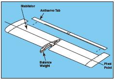
[Figure 4-9. The stabilator is a one-piece horizontal tail surface that pivots up and down about a central hinge point.]
When the control column is pulled back, it raises the stabilator’s trailing edge, rotating the airplane’s nose up. Pushing the control column forward lowers the trailing edge of the stabilator and pitches the nose of the airplane down. Without an antiservo tab, the airplane would be prone to overcontrolling from pilot-induced control inputs.
CANARD
The term canard refers to a control surface that functions as a horizontal stabilizer but is located in front of the main wings. The term also is used to describe an airplane equipped with a canard. In effect, it is an airfoil similar to the horizontal surface on a conventional aft-tail design. The difference is that the canard actually creates lift and holds the nose up, as opposed to the aft-tail design which exerts downward force on the tail to prevent the nose from rotating downward.
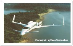
[Figure 4-10. This advanced aircraft includes a variable-sweep canard design, which provides longitudinal stability about the lateral axis.]
Canard—A horizontal surface mounted ahead of the main wing to provide longitudinal stability and control. It may be a fixed, movable, or variable geometry surface, with or without control surfaces.
Canard Configuration—A configuration in which the span of the forward wings is substantially less than that of the main wing.
Although the Wright Flyer was configured as a canard with the horizontal surfaces in front of the lifting surface, it was not until recently that the canard configuration began appearing on newer airplanes. Canard designs include two types—one with a horizontal surface of about the same size as a normal aft-tail design, and the other with a surface of the same approximate size and airfoil of the aft-mounted wing known as a tandem wing configuration. Theoretically, the canard is considered more efficient because using the horizontal surface to help lift the weight of the aircraft should result in less drag for a given amount of lift.
The canard’s main advantage is in the area of stall characteristics. A properly designed canard or tandem wing will run out of authority to raise the nose of the aircraft at a point before the main wing will stall. This makes the aircraft stall-proof and results only in a descent rate that can be halted by adding power. Ailerons on the main wing remain effective throughout the recovery. Other canard configurations are designed so the canard stalls before the main wing, automatically lowering the nose and recovering the aircraft to a safe flying speed. Again, the ailerons remain effective throughout the stall.
The canard design has several limitations. First, it is important that the forward lifting surface of a canard design stalls before the main wing. If the main wing stalls first, the lift remaining from the forward wing or canard would be well ahead of the CG, and the airplane would pitch up uncontrollably. Second, when the forward surface stalls first, or is limited in its ability to increase the angle of attack, the main wing never reaches a point where its maximum lift is created, sacrificing some performance. Third, use of flaps on the main wing causes design problems for the forward wing or canard. As lift on the main wing is increased by extension of flaps, the lift requirement of the canard is also increased. The forward wing or canard must be large enough to accommodate flap use, but not so large that it creates more lift than the main wing.
Finally, the relationship of the main wing to the forward surface also makes a difference. When positioned closely in the vertical plane, downwash from the forward wing can have a negative effect on the lift of the main wing. Increasing vertical separation increases efficiency of the design. Efficiency is also increased as the size of the two surfaces grows closer to being equal.
RUDDER
The rudder controls movement of the airplane about its vertical axis. This motion is called yaw. Like the
Figure 4-10. This advanced aircraft includes a variable-sweep canard design, which provides longitudinal stability about the lateral axis.
other primary control surfaces, the rudder is a movable surface hinged to a fixed surface, in this case, to the vertical stabilizer, or fin. Moving the left or right rudder pedal controls the rudder. When the rudder is deflected into the airflow, a horizontal force is exerted in the opposite direction.
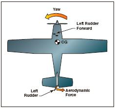
[Figure 4-11. The effect of left rudder pressure.]
By pushing the left pedal, the rudder moves left. This alters the airflow around the vertical stabilizer/rudder, and creates a sideward lift that moves the tail to the right and yaws the nose of the airplane to the left. Rudder effectiveness increases with speed, so large deflections at low speeds and small deflections at high speeds may be required to provide the desired reaction. In propeller-driven aircraft, any slipstream flowing over the rudder increases its effectiveness.
V-TAIL
The V-tail design utilizes two slanted tail surfaces to perform the same functions as the surfaces of a conventional elevator and rudder configuration. The fixed surfaces act as both horizontal and vertical stabilizers.
[Figure 4-12. V-tail design.]
The movable surfaces, which are usually called ruddervators, are connected through a special linkage that allows the control wheel to move both surfaces simultaneously. On the other hand, displacement of the rudder pedals moves the surfaces differentially, thereby providing directional control.
When both rudder and elevator controls are moved by the pilot, a control mixing mechanism moves each surface the appropriate amount. The control system for the V-tail is more complex than that required for a conventional tail. In addition, the V-tail design is more susceptible to Dutch roll tendencies than a conventional tail and total reduction in drag is only minimal.