Airplane Ground Schools
Knowledge of Flying is Our passion.
Serving the General Aviation Community
GENERAL
This chapter contains an overview of jet powered airplane operations. It is not meant to replace any portion of a formal jet airplane qualification course. Rather, the information contained in this chapter is meant to be a useful preparation for and a supplement to formal and structured jet airplane qualification training. The intent of this chapter is to provide information on the major differences a pilot will encounter when transitioning to jet powered airplanes. In order to achieve this in a logical manner, the major differences between jet powered airplanes and piston powered airplanes have been approached by addressing two distinct areas: differences in technology, or how the airplane itself differs; and differences in pilot technique, or how the pilot deals with the technological differences through the application of different techniques. If any of the information in this chapter conflicts with information contained in the FAA-approved Airplane Flight Manual for a particular airplane, the Airplane Flight Manual takes precedence.
JET ENGINE BASICS
A jet engine is a gas turbine engine. A jet engine develops thrust by accelerating a relatively small mass of air to very high velocity, as opposed to a propeller, which develops thrust by accelerating a much larger mass of air to a much slower velocity. As stated in Transition to Complex Airplanes, both piston and gas turbine engines are internal combustion engines and have a similar basic cycle of operation; that is, induction, compression, combustion, expansion, and exhaust. Air is taken in and compressed, and fuel is injected and burned. The hot gases then expand and supply a surplus of power over that required for compression, and are finally exhausted. In both piston and jet engines, the efficiency of the cycle is improved by increasing the volume of air taken in and the compression ratio.
Part of the expansion of the burned gases takes place in the turbine section of the jet engine providing the necessary power to drive the compressor, while the remainder of the expansion takes place in the nozzle of the tail pipe in order to accelerate the gas to a high velocity jet thereby producing thrust.
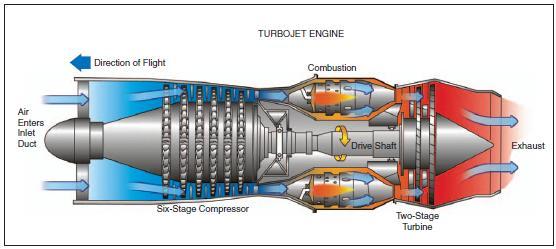
[Figure 15-1 Basic turbojet engine]
In theory, the jet engine is simpler and more directly converts thermal energy (the burning and expansion of gases) into mechanical energy (thrust). The piston or reciprocating engine, with all of its moving parts, must convert the thermal energy into mechanical energy and then finally into thrust by rotating a propeller.
One of the advantages of the jet engine over the piston engine is the jet engine’s capability of producing much greater amounts of thrust horsepower at the high altitudes and high speeds. In fact, turbojet engine efficiency increases with altitude and speed. Direction of Flight Air Enters Inlet Duct Exhaust Combustion Drive Shaft Six-Stage Compressor
Although the propeller driven airplane is not nearly as efficient as the jet, particularly at the higher altitudes and cruising speeds required in modern aviation, one of the few advantages the propeller driven airplane has over the jet is that maximum thrust is available almost at the start of the takeoff roll. Initial thrust output of the jet engine on takeoff is relatively lower and does not reach peak efficiency until the higher speeds. The fanjet or turbofan engine was developed to help compensate for this problem and is, in effect, a compromise between the pure jet engine (turbojet) and the propeller engine.
Like other gas turbine engines, the heart of the turbofan engine is the gas generator—the part of the engine that produces the hot, high-velocity gases. Similar to turboprops, turbofans have a low pressure turbine section that uses most of the energy produced by the gas generator. The low pressure turbine is mounted on a concentric shaft that passes through the hollow shaft of the gas generator, connecting it to a ducted fan at the front of the engine.
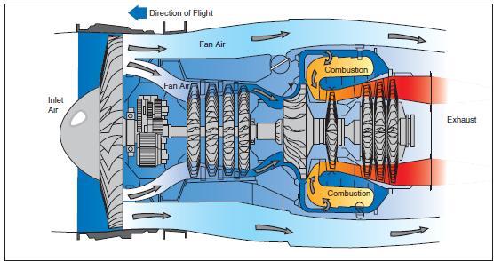
[Figure 15-2 Turbofan engine]
Air enters the engine, passes through the fan, and splits into two separate paths. Some of it flows around— bypasses—the engine core, hence its name, bypass air. The air drawn into the engine for the gas generator is the core airflow. The amount of air that bypasses the core compared to the amount drawn into the gas generator determines a turbofan’s bypass ratio. Turbofans efficiently convert fuel into thrust because they produce low pressure energy spread over a large fan disk area. While a turbojet engine uses all of the gas generator’s output to produce thrust in the form of a high-velocity exhaust gas jet, cool, low-velocity bypass air produces between 30 percent and 70 percent of the thrust produced by a turbofan engine.
The fan-jet concept increases the total thrust of the jet engine, particularly at the lower speeds and altitudes. Although efficiency at the higher altitudes is lost (turbofan engines are subject to a large lapse in thrust with increasing altitude), the turbofan engine increases acceleration, decreases the takeoff roll, improves initial climb performance, and often has the effect of decreasing specific fuel consumption.
OPERATING THE JET ENGINE
In a jet engine, thrust is determined by the amount of fuel injected into the combustion chamber. The power controls on most turbojet and turbofan powered airplanes consist of just one thrust lever for each engine, because most engine control functions are automatic. The thrust lever is linked to a fuel control and/or electronic engine computer that meters fuel flow based upon r.p.m., internal temperatures, ambient conditions, and other factors.
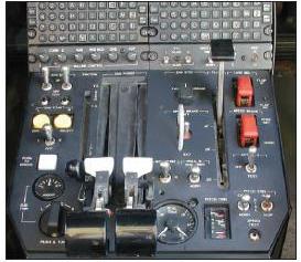
[Figure 15-3 Jet engine power controls]
In a jet engine, each major rotating section usually has a separate gauge devoted to monitoring its speed of rotation. Depending on the make and model, a jet engine may have an N1 gauge that monitors the low pressure compressor section and/or fan speed in turbofan engines. The gas generator section may be monitored by an N2 gauge, while triple spool engines may have an N3 gauge as well. Each engine section rotates at many thousands of r.p.m. Their gauges therefore are calibrated in percent of r.p.m. rather than actual r.p.m., for ease of display and interpretation.
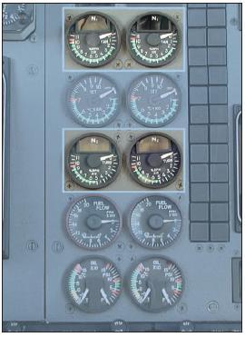
[Figure 15-4 Jet engine r.p.m. gauges]
Direction of Flight Inlet Air Exhaust Combustion Combustion Fan Air Fan Air Figure 15-2.Turbofan engine. The temperature of turbine gases must be closely monitored by the pilot. As in any gas turbine engine, exceeding temperature limits, even for a very few seconds, may result in serious heat damage to turbine blades and other components. Depending on the make and model, gas temperatures can be measured at a number of different locations within the engine. The associated engine gauges therefore have different names according to their location. For instance:
• Exhaust Gas Temperature (EGT)—the temperature of the exhaust gases as they enter the tail pipe, after passing through the turbine.
• Turbine Inlet Temperature (TIT)—the temperature of the gases from the combustion section of the engine as they enter the first stage of the turbine. TIT is the highest temperature inside a gas turbine engine and is one of the limiting factors of the amount of power the engine can produce. TIT, however, is difficult to measure. EGT therefore, which relates to TIT, is normally the parameter measured.
• Interstage Turbine Temperature (ITT)—the temperature of the gases between the high pressure and low pressure turbine wheels.
• Turbine Outlet Temperature (TOT)—like EGT, turbine outlet temperature is taken aft of the turbine wheel(s).
JET ENGINE IGNITION
Most jet engine ignition systems consist of two igniter plugs, which are used during the ground or air starting of the engine. Once the start is completed, this ignition either automatically goes off or is turned off, and from this point on, the combustion in the engine is a continuous process.
CONTINUOUS IGNITION
An engine is sensitive to the flow characteristics of the air that enters the intake of the engine nacelle. So long as the flow of air is substantially normal, the engine will continue to run smoothly. However, particularly with rear mounted engines that are sometimes in a position to be affected by disturbed airflow from the wings, there are some abnormal flight situations that could cause a compressor stall or flameout of the engine. These abnormal flight conditions would usually be associated with abrupt pitch changes such as might be encountered in severe turbulence or a stall.
In order to avoid the possibility of engine flameout from the above conditions, or from other conditions that might cause ingestion problems such as heavy rain, ice, or possible bird strike, most jet engines are equipped with a continuous ignition system. This system can be turned on and used continuously whenever the need arises. In many jets, as an added precaution, this system is normally used during takeoffs and landings. Many jets are also equipped with an automatic ignition system that operates both igniters whenever the airplane stall warning or stick shaker is activated.
FUEL HEATERS
Because of the high altitudes and extremely cold outside air temperatures in which the jet flies, it is possible to supercool the jet fuel to the point that the small Figure 15-3. Jet engine power controls. Figure 15-4. Jet engine r.p.m. gauges particles of water suspended in the fuel can turn to ice crystals and clog the fuel filters leading to the engine. For this reason, jet engines are normally equipped with fuel heaters. The fuel heater may be of the automatic type which constantly maintains the fuel temperature above freezing, or they may be manually controlled by the pilot from the cockpit.
SETTING POWER
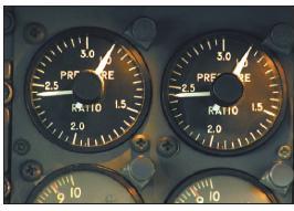
On some jet airplanes, thrust is indicated by an engine pressure ratio (EPR) gauge. Engine pressure ratio can be thought of as being equivalent to the manifold pressure on the piston engine. Engine pressure ratio is the difference between turbine discharge pressure and engine inlet pressure. It is an indication of what the engine has done with the raw air scooped in. For instance, an EPR setting of 2.24 means that the discharge pressure relative to the inlet pressure is 2.24 : 1. On these airplanes, the EPR gauge is the primary reference used to establish power settings.
[Figure 15-5 EPR gauge]
Fan speed (N1) is the primary indication of thrust on most turbofan engines. Fuel flow provides a secondary thrust indication, and cross-checking for proper fuel flow can help in spotting a faulty N1 gauge. Turbofans also have a gas generator turbine tachometer (N2). They are used mainly for engine starting and some system functions.
In setting power, it is usually the primary power reference (EPR or N1) that is most critical, and will be the gauge that will first limit the forward movement of the thrust levers. However, there are occasions where the limits of either r.p.m. or temperature can be exceeded. The rule is: movement of the thrust levers must be stopped and power set at whichever the limits of EPR, r.p.m., or temperature is reached first.
THRUST TO THRUST LEVER RELATIONSHIP
In a piston engine propeller driven airplane, thrust is proportional to r.p.m., manifold pressure, and propeller blade angle, with manifold pressure being the most dominant factor. At a constant r.p.m., thrust is proportional to throttle lever position. In a jet engine, however, thrust is quite disproportional to thrust lever position. This is an important difference that the pilot transitioning into jet powered airplanes must become accustomed to.
On a jet engine, thrust is proportional to r.p.m. (mass flow) and temperature (fuel/air ratio). These are matched and a further variation of thrust results from the compressor efficiency at varying r.p.m. The jet engine is most efficient at high r.p.m., where the engine is designed to be operated most of the time. As r.p.m. increases, mass flow, temperature, and efficiency also increase. Therefore, much more thrust is produced per increment of throttle movement near the top of the range than near the bottom.
One thing that will seem different to the piston pilot transitioning into jet powered airplanes is the rather large amount of thrust lever movement between the flight idle position and full power as compared to the small amount of movement of the throttle in the piston engine. For instance, an inch of throttle movement on a piston may be worth 400 horsepower wherever the throttle may be. On a jet, an inch of thrust lever movement at a low r.p.m. may be worth only 200 pounds of thrust, but at a high r.p.m. that same inch of movement might amount to closer to 2,000 pounds of thrust. Because of this, in a situation where significantly more thrust is needed and the jet engine is at low r.p.m., it will not do much good to merely “inch the thrust lever forward.” Substantial thrust lever movement is in order. This is not to say that rough or abrupt thrust lever action is standard operating procedure. If the power setting is already high, it may take only a small amount of movement. However, there are two characteristics of the jet engine that work against the normal habits of the piston engine pilot. One is the variation of thrust with r.p.m., and the other is the relatively slow acceleration of the jet engine.
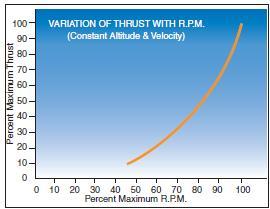
VARIATION OF THRUST WITH RPM
Whereas piston engines normally operate in the range of 40 percent to 70 percent of available r.p.m., jets operate most efficiently in the 85 percent to 100 percent range, with a flight idle r.p.m. of 50 percent to 60 percent. The range from 90 percent to 100 percent in jets may produce as much thrust as the total available at 70 percent.
[Figure 15-6 Variation of thrust with r.p.m.]
SLOW ACCELERATION OF THE JET ENGINE
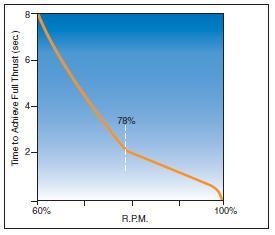
In a propeller driven airplane, the constant speed propeller keeps the engine turning at a constant r.p.m. within the governing range, and power is changed by varying the manifold pressure. Acceleration of the piston from idle to full power is relatively rapid, somewhere on the order of 3 to 4 seconds. The acceleration on the different jet engines can vary considerably, but it is usually much slower. Efficiency in a jet engine is highest at high r.p.m. where the compressor is working closest to its optimum conditions. At low r.p.m. the operating cycle is generally inefficient. If the engine is operating at normal approach r.p.m. and there is a sudden requirement for increased thrust, the jet engine will respond immediately and full thrust can be achieved in about 2 seconds. However, at a low r.p.m., sudden full power application will tend to overfuel the engine resulting in possible compressor surge, excessive turbine temperatures, compressor stall and/or flameout. To prevent this, various limiters such as compressor bleed valves are contained in the system and serve to restrict the engine until it is at an r.p.m. at which it can respond to a rapid acceleration demand without distress. This critical r.p.m. is most noticeable when the engine is at idle r.p.m. and the thrust lever is rapidly advanced to a high power position. Engine acceleration is initially very slow, but changes to very fast after about 78 percent r.p.m. is reached.
[Figure 15-7 Typical Jet engine acceleration times]
Even though engine acceleration is nearly instantaneous after about 78 percent r.p.m., total time to accelerate from idle r.p.m. to full power may take as much as 8 seconds. For this reason, most jets are operated at a relatively high r.p.m. during the final approach to landing or at any other time that immediate power may be needed.
JET ENGINE EFFICIENCY
Maximum operating altitudes for general aviation turbojet airplanes now reach 51,000 feet. The efficiency of the jet engine at high altitudes is the primary reason for operating in the high altitude environment. The specific fuel consumption of jet engines decreases as the outside air temperature decreases for constant engine r.p.m. and true airspeed (TAS). Thus, by flying at a high altitude, the pilot is able to operate at flight levels where fuel economy is best and with the most advantageous cruise speed. For efficiency, jet airplanes are typically operated at high altitudes where cruise is usually very close to r.p.m or exhaust gas temperature limits. At high altitudes, little excess thrust may be available for maneuvering. Therefore, it is often impossible for the jet airplane to climb and turn simultaneously, and all maneuvering must be accomplished within the limits of available thrust and without sacrificing stability and controllability.
ABSENCE OF PROPELLER EFFECT
The absence of a propeller has a significant effect on the operation of jet powered airplanes that the transitioning pilot must become accustomed to. The effect is due to the absence of lift from the propeller slipstream, and the absence of propeller drag.
ABSENCE OF PROPELLER SLIPSTREAM
A propeller produces thrust by accelerating a large mass of air rearwards, and (especially with wing mounted engines) this air passes over a comparatively large percentage of the wing area. On a propeller driven airplane, the lift that the wing develops is the sum of the lift generated by the wing area not in the wake of the propeller (as a result of airplane speed) and the lift generated by the wing area influenced by the propeller slipstream. By increasing or decreasing the speed of the slipstream air, therefore, it is possible to increase or decrease the total lift on the wing without changing airspeed.
For example, a propeller driven airplane that is allowed to become too low and too slow on an approach is very responsive to a quick blast of power to salvage the situation. In addition to increasing lift at a constant airspeed, stalling speed is reduced with power on. Ajet engine, on the other hand, also produces thrust by accelerating a mass of air rearward, but this air does not pass over the wings. There is therefore no lift bonus at increased power at constant airspeed, and no significant lowering of power-on stall speed.
In not having propellers, the jet powered airplane is minus two assets.
• It is not possible to produce increased lift instantly by simply increasing power.
• It is not possible to lower stall speed by simply increasing power. The 10-knot margin (roughly the difference between power-off and power-on stall speed on a propeller driven airplane for a given configuration) is lost. Add the poor acceleration response of the jet engine and it becomes apparent that there are three ways in which the jet pilot is worse off than the propeller pilot. For these reasons, there is a marked difference between the approach qualities of a piston engine airplane and a jet. In a piston engine airplane, there is some room for error. Speed is not too critical and a burst of power will salvage an increasing sink rate. In a jet, however, there is little room for error.
If an increasing sink rate develops in a jet, the pilot must remember two points in the proper sequence.
1. Increased lift can be gained only by accelerating airflow over the wings, and this can be accomplished only by accelerating the entire airplane.
2. The airplane can be accelerated, assuming altitude loss cannot be afforded, only by a rapid increase in thrust, and here, the slow acceleration of the jet engine (possibly up to 8 seconds) becomes a factor.
Salvaging an increasing sink rate on an approach in a jet can be a very difficult maneuver. The lack of ability to produce instant lift in the jet, along with the slow acceleration of the engine, necessitates a “stabilized approach” to a landing where full landing configuration, constant airspeed, controlled rate of descent, and relatively high power settings are maintained until over the threshold of the runway. This allows for almost immediate response from the engine in making minor changes in the approach speed or rate of descent and makes it possible to initiate an immediate go-around or missed approach if necessary.
ABSENCE OF PROPELLER DRAG
When the throttles are closed on a piston powered airplane, the propellers create a vast amount of drag, and airspeed is immediately decreased or altitude lost. The effect of reducing power to idle on the jet engine, however, produces no such drag effect. In fact, at an idle power setting, the jet engine still produces forward thrust. The main advantage is that the jet pilot is no longer faced with a potential drag penalty of a runaway propeller, or a reversed propeller. A disadvantage, however, is the “free wheeling” effect forward thrust at idle has on the jet. While this occasionally can be used to advantage (such as in a long descent), it is a handicap when it is necessary to lose speed quickly, such as when entering a terminal area or when in a landing flare. The lack of propeller drag, along with the aerodynamically clean airframe of the jet, are new to most pilots, and slowing the airplane down is one of the initial problems encountered by pilots transitioning into jets.
SPEED MARGINS
The typical piston powered airplane had to deal with two maximum operating speeds.
• VNO—Maximum structural cruising speed, represented on the airspeed indicator by the upper limit of the green arc. It is, however, permissible to exceed VNO and operate in the caution range (yellow arc) in certain flight conditions.
• VNE—Never-exceed speed, represented by a red line on the airspeed indicator.
These speed margins in the piston airplanes were never of much concern during normal operations because the high drag factors and relatively low cruise power settings kept speeds well below these maximum limits.
Maximum speeds in jet airplanes are expressed differently, and always define the maximum operating speed of the airplane which is comparable to the VNE of the piston airplane. These maximum speeds in a jet airplane are referred to as:
• VMO—Maximum operating speed expressed in terms of knots.
• MMO—Maximum operating speed expressed in terms of a decimal of Mach speed (speed of sound).
To observe both limits VMO and MMO, the pilot of a jet airplane needs both an airspeed indicator and a Machmeter, each with appropriate red lines. In some general aviation jet airplanes, these are combined into a single instrument that contains a pair of concentric indicators, one for the indicated airspeed and the other for indicated Mach number. Each is provided with an appropriate red line.
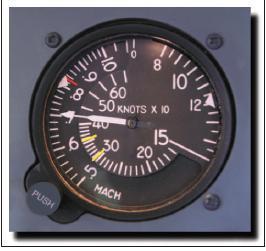
[Figure 15-8 Jet airspeed indicator]
A more sophisticated indicator is used on most jetliners. It looks much like a conventional airspeed indicator but has a “barber pole” that automatically moves so as to display the applicable speed limit at all times.
Because of the higher available thrust and very low drag design, the jet airplane can very easily exceed its speed margin even in cruising flight, and in fact in some airplanes in a shallow climb. The handling qualities in a jet can change drastically when the maximum operating speeds are exceeded.
High speed airplanes designed for subsonic flight are limited to some Mach number below the speed of sound to avoid the formation of shock waves that begin to develop as the airplane nears Mach 1.0. These shock waves (and the adverse effects associated with them) can occur when the airplane speed is substantially below Mach 1.0. The Mach speed at which some portion of the airflow over the wing first equals Mach 1.0 is termed the critical Mach number (MACHCRIT). This is also the speed at which a shock wave first appears on the airplane.
There is no particular problem associated with the acceleration of the airflow up to the point where Mach 1.0 is encountered; however, a shock wave is formed at the point where the airflow suddenly returns to subsonic flow. This shock wave becomes more severe and moves aft on the wing as speed of the wing is increased, and eventually flow separation occurs behind the well-developed shock wave.
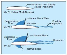
[Figure 15-9 Transonic flow patterns]
If allowed to progress well beyond the MMO for the airplane, this separation of air behind the shock wave can result in severe buffeting and possible loss of control or “upset.”
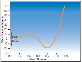
Because of the changing center of lift of the wing resulting from the movement of the shock wave, the pilot will experience pitch change tendencies as the airplane moves through the transonic speeds up to and exceeding MMO.
[Figure 15-10 Example of Stick Forces vs. Mach Number in a
typical jet airplane]
For example, as the graph in figure 15-10 illustrates, initially as speed is increased up to Mach .72 the wing develops an increasing amount of lift requiring a nosedown force or trim to maintain level flight. With increased speed and the aft movement of the shock wave, the wing’s center of pressure also moves aft causing the start of a nosedown tendency or “tuck.” By Mach .83 the nosedown forces are well developed to a point where a total of 70 pounds of back pressure are required to hold the nose up. If allowed to progress unchecked, Mach tuck may eventually occur. Although Mach tuck develops gradually, if it is allowed to progress significantly, the center of pressure can move so far rearward that there is no longer enough elevator authority available to counteract it, and the airplane could enter a steep, sometimes unrecoverable dive.
An alert pilot would have observed the high airspeed indications, experienced the onset of buffeting, and responded to aural warning devices long before encountering the extreme stick forces shown. However, in the event that corrective action is not taken and the nose allowed to drop, increasing airspeed even further, the situation could rapidly become dangerous. As the Mach speed increases beyond the airplane’s MMO, the effects of flow separation and turbulence behind the shock wave become more severe. Eventually, the most powerful forces causing Mach tuck are a result of the buffeting and lack of effective downwash on the horizontal stabilizer because of the disturbed airflow over the wing. This is the primary reason for the development of the T-tail configuration on some jet airplanes, which places the horizontal stabilizer as far as practical from the turbulence of the wings. Also, because of the critical aspects of high-altitude/high-Mach flight, most jet airplanes capable of operating in the Mach speed ranges are designed with some form of trim and autopilot Mach compensating device (stick puller) to alert the pilot to inadvertent excursions beyond its certificated MMO.
RECOVERY FROM OVERSPEED CONDITIONS
The simplest remedy for an overspeed condition is to ensure that the situation never occurs in the first place. For this reason, the pilot must be aware of all the conditions that could lead to exceeding the airplane’s maximum operating speeds. Good attitude instrument flying skills and good power control are essential.
The pilot should be aware of the symptoms that will be experienced in the particular airplane as the VMO or MMO is being approached. These may include:
• Nosedown tendency and need for back pressure or trim.
• Mild buffeting as airflow separation begins to occur after critical Mach speed.
• Actuation of an aural warning device/stick puller at or just slightly beyond VMO or MMO.
The pilot’s response to an overspeed condition should be to immediately slow the airplane by reducing the power to flight idle. It will also help to smoothly and easily raise the pitch attitude to help dissipate speed (in fact this is done automatically through the stick puller device when the high speed warning system is activated). The use of speed brakes can also aid in slowing the airplane. If, however, the nosedown stick forces have progressed to the extent that they are excessive, some speed brakes will tend to further aggravate the nosedown tendency. Under most conditions, this additional pitch down force is easily controllable, and since speed brakes can normally be used at any speed, they are a very real asset. A final option would be to extend the landing gear. This will create enormous drag and possibly some noseup pitch, but there is usually little risk of damage to the gear itself. The pilot transitioning into jet airplanes must be familiar with the manufacturers’ recommended procedures for dealing with overspeed conditions contained in the FAA-approved Airplane Flight Manual for the particular make and model airplane.
MACH BUFFET BOUNDARIES
Thus far, only the Mach buffet that results from excessive speed has been addressed. The transitioning pilot, however, should be aware that Mach buffet is a function of the speed of the airflow over the wing— not necessarily the airspeed of the airplane. Anytime that too great a lift demand is made on the wing, whether from too fast an airspeed or from too high an angle of attack near the MMO, the “high speed buffet” will occur. However, there are also occasions when the buffet can be experienced at much slower speeds known as “low speed Mach buffet.”
The most likely situations that could cause the low speed buffet would be when an airplane is flown at too slow a speed for its weight and altitude causing a high angle of attack. This very high angle of attack would have the same effect of increasing airflow over the upper surface of the wing to the point that all of the same effects of the shock waves and buffet would occur as in the high speed buffet situation. The angle of attack of the wing has the greatest effect on inducing the Mach buffet at either the high or low speed boundaries for the airplane. The conditions that increase the angle of attack, hence the speed of the airflow over the wing and chances of Mach buffet are:
• High altitudes—The higher the airplane flies, the thinner the air and the greater the angle of attack required to produce the lift needed to maintain level flight.
• Heavy weights—The heavier the airplane, the greater the lift required of the wing, and all other things being equal, the greater the angle of attack.
• “G” loading—An increase in the “G” loading of the wing results in the same situation as increasing the weight of the airplane. It makes no difference whether the increase in “G” forces is caused by a turn, rough control usage, or turbulence. The effect of increasing the wing’s angle of attack is the same. An airplane’s indicated airspeed decreases in relation to true airspeed as altitude increases.
As the indicated airspeed decreases with altitude, it progressively merges with the low speed buffet boundary where prestall buffet occurs for the airplane at a load factor of 1.0 G. The point where the high speed Mach indicated airspeed and low speed buffet boundary indicated airspeed merge is the airplane’s absolute or aerodynamic ceiling. Once an airplane has reached its aerodynamic ceiling, which is higher than the altitude stipulated in the FAA-approved Airplane Flight Manual, the airplane can neither be made to go faster without activating the design stick puller at Mach limit nor can it be made to go slower without activating the stick shaker or stick pusher. This critical area of the airplane’s flight envelope is known as “coffin corner.”
Mach buffet occurs as a result of supersonic airflow on the wing. Stall buffet occurs at angles of attack that produce airflow disturbances (burbling) over the upper surface of the wing which decreases lift. As density altitude increases, the angle of attack that is required to produce an airflow disturbance over the top of the wing is reduced until the density altitude is reached where Mach buffet and stall buffet converge (coffin corner). When this phenomenon is encountered, serious consequences may result causing loss of airplane control.
Increasing either gross weight or load factor (G factor) will increase the low speed buffet and decrease Mach buffet speeds. A typical jet airplane flying at 51,000 feet altitude at 1.0 G may encounter Mach buffet slightly above the airplane’s MMO (.82 Mach) and low speed buffet at .60 Mach. However, only 1.4 G (an increase of only 0.4 G) may bring on buffet at the optimum speed of .73 Mach and any change in airspeed, bank angle, or gust loading may reduce this straightand- level flight 1.4 G protection to no protection at all. Consequently, a maximum cruising flight altitude must be selected which will allow sufficient buffet margin for necessary maneuvering and for gust conditions likely to be encountered. Therefore, it is important for pilots to be familiar with the use of charts showing cruise maneuver and buffet limits.
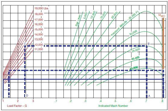
[Figure 15-11 Mach buffet boundary chart]
The transitioning pilot must bear in mind that the maneuverability of the jet airplane is particularly critical, especially at the high altitudes. Some jet airplanes have a very narrow span between the high and low speed buffets. One airspeed that the pilot should have firmly fixed in memory is the manufacturer’s recommended gust penetration speed for the particular make and model airplane. This speed is normally the speed that would give the greatest margin between the high and low speed buffets, and may be considerably higher than design maneuvering speed (VA). This means that, unlike piston airplanes, there are times when a jet airplane should be flown in excess of VA during encounters with turbulence. Pilots operating airplanes at high speeds must be adequately trained to operate them safely. This training cannot be complete until pilots are thoroughly educated in the critical aspects of the aerodynamic factors pertinent to Mach flight at high altitudes.
LOW SPEED FLIGHT
The jet airplane wing, designed primarily for high speed flight, has relatively poor low speed characteristics. As opposed to the normal piston powered airplane, the jet wing has less area, a lower aspect ratio (long chord/short span), and thin airfoil shape—all of which amount to less lift. The sweptwing is additionally penalized at low speeds because the effective lift, which is perpendicular to the leading edge, is always less than the airspeed of the airplane itself. In other words, the airflow on the sweptwing has the effect of persuading the wing into believing that it is flying slower than it actually is, but the wing consequently suffers a loss of lift for a given airspeed at a given angle of attack.
The first real consequence of poor lift at low speeds is a high stall speed. The second consequence of poor lift at low speeds is the manner in which lift and drag vary with speed in the lower ranges. As a jet airplane is slowed toward its minimum drag speed (VMD or L/DMAX), total drag increases at a much greater rate than lift, resulting in a sinking flightpath. If the pilot attempts to increase lift by increasing pitch attitude, airspeed will be further reduced resulting in a further increase in drag and sink rate as the airplane slides up the back side of the power curve. The sink rate can be arrested in one of two ways:
• Pitch attitude can be substantially reduced to reduce the angle of attack and allow the airplane to accelerate to a speed above VMD, where steady flight conditions can be reestablished. This procedure, however, will invariably result in a substantial loss of altitude.
• Thrust can be increased to accelerate the airplane to a speed above VMD to reestablish steady flight conditions. It should be remembered that the amount of thrust required will be quite large. The amount of thrust must be sufficient to accelerate the airplane and regain altitude lost. Also, if the airplane has slid a long way up the back side of the power required (drag) curve, drag will be very high and a very large amount of thrust will be required. In a typical piston engine airplane, VMD in the clean configuration is normally at a speed of about 1.3 VS.
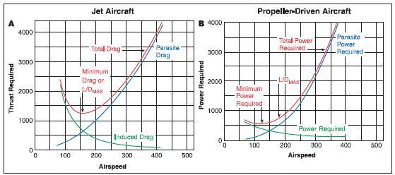
[Figure 15-12 Thrust and power required curves]
Flight below VMD on a piston engine airplane is well identified and predictable. In contrast, in a jet airplane flight in the area of VMD (typically 1.5 – 1.6 VS) does not normally produce any noticeable changes in flying qualities other than a lack of speed stability—a condition where a decrease in speed leads to an increase in drag which leads to a further decrease in speed and hence a speed divergence. A pilot who is not cognizant of a developing speed divergence may find a serious sink rate developing at a constant power setting, and a pitch attitude that appears to be normal. The fact that drag increases more rapidly than lift, causing a sinking flightpath, is one of the most important aspects of jet airplane flying qualities.
STALLS
The stalling characteristics of the sweptwing jet airplane can vary considerably from those of the normal straight wing airplane. The greatest difference that will be noticeable to the pilot is the lift developed vs. angle of attack. An increase in angle of attack of the straight wing produces a substantial and constantly increasing lift vector up to its maximum coefficient of lift, and soon thereafter flow separation (stall) occurs with a rapid deterioration of lift.
By contrast, the sweptwing produces a much more gradual buildup of lift with no well defined maximum coefficient and has the ability to fly well beyond this maximum buildup even though lift is lost. The drag curves (which are not depicted in figure 15-13) are approximately the reverse of the lift curves shown, in that a rapid increase in drag component may be expected with an increase in the angle of attack of a sweptwing airplane.

[Figure 15-13. Stall vs. angle of attack—sweptwing vs. straight
wing]
The differences in the stall characteristics between a conventional straight wing/low tailplane (non T-tail) airplane and a sweptwing T-tail airplane center around two main areas.
• The basic pitching tendency of the airplane at the stall.
• Tail effectiveness in stall recovery.
On a conventional straight wing/low tailplane airplane, the weight of the airplane acts downwards forward of the lift acting upwards, producing a need for a balancing force acting downwards from the tailplane. As speed is reduced by gentle up elevator deflection, the static stability of the airplane causes a nosedown tendency. This is countered by further up elevator to keep the nose coming up and the speed decreasing. As the pitch attitude increases, the low set tail is immersed in the wing wake, which is slightly turbulent, low energy air. The accompanying aerodynamic buffeting serves as a warning of impending stall. The reduced effectiveness of the tail prevents the pilot from forcing the airplane into a deeper stall.

[Figure 15-14 Stall progression—typical straight wing
airplane]
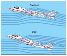
The conventional straight wing airplane conforms to the familiar nosedown pitching tendency at the stall and gives the entire airplane a fairly pronounced nosedown pitch. At the moment of stall, the wing wake passes more or less straight rearward and passes above the tail. The tail is now immersed in high energy air where it experiences a sharp increase in positive angle of attack causing upward lift. This lift then assists the nosedown pitch and decrease in wing angle of attack essential to stall recovery. In a sweptwing jet with a T-tail and rear fuselage mounted engines, the two qualities that are different from its straight wing low tailplane counterpart are the pitching tendency of the airplane as the stall develops and the loss of tail effectiveness at the stall. The handling qualities down to the stall are much the same as the straight wing airplane except that the high, T-tail remains clear of the wing wake and provides little or no warning in the form of a pre-stall buffet. Also, the tail is fully effective during the speed reduction towards the stall, and remains effective even after the wing has begun to stall. This enables the pilot to drive the wing into a deeper stall at a much greater angle of attack.
At the stall, two distinct things happen. After the stall, the sweptwing T-tail airplane tends to pitch up rather than down, and the T-tail is immersed in the wing wake, which is low energy turbulent air. This greatly reduces tail effectiveness and the airplane’s ability to counter the noseup pitch. Also, the disturbed, relatively slow air behind the wing may sweep across the tail at such a large angle that the tail itself stalls. If this occurs, the pilot loses all pitch control and will be unable to lower the nose. The pitch up just after the stall is worsened by large reduction in lift and a large increase in drag, which causes a rapidly increasing descent path, thus compounding the rate of increase of the wing’s angle of attack.
[Figure 15-15 Stall progression sweptwing airplane]
The pitch up tendency after the stall is a characteristic of a swept and/or tapered wings. With these types of wings, there is a tendency for the wing to develop a strong spanwise airflow towards the wingtip when the wing is at high angles of attack. This leads to a tendency for separation of airflow, and the subsequent stall, to occur at the wingtips first.
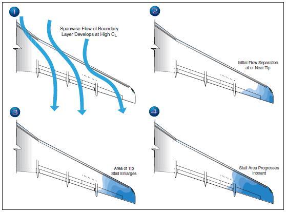
[Figure 15-16 Sweptwing stall characteristics]
The tip first stall, results in a shift of the center of lift of the wing in a forward direction relative to the center of gravity of the airplane, causing the nose to pitch up. Another disadvantage of a tip first stall is that it can involve the ailerons and erode roll control. As previously stated, when flying at a speed in the area of VMD, an increase in angle of attack causes drag to increase faster than lift and the airplane begins to sink. It is essential to understand that this increasing sinking tendency, at a constant pitch attitude, results in a rapid increase in angle of attack as the flightpath becomes deflected downwards.
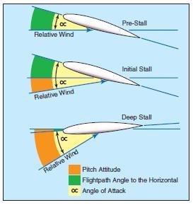
[Figure 15-17 Deep stall progression]
Furthermore, once the stall has developed and a large amount of lift has been lost, the airplane will begin to sink rapidly and this will be accompanied by a corresponding rapid increase in angle of attack. This is the beginning of what is termed a deep stall. As an airplane enters a deep stall, increasing drag reduces forward speed to well below normal stall speed. The sink rate may increase to many thousands of feet per minute. The airplane eventually stabilizes in a vertical descent. The angle of attack may approach 90° and the indicated airspeed may be reduced to zero. At a 90° angle of attack, none of the airplane’s control surfaces are effective. It must be emphasized that this situation can occur without an excessively nose-high pitch attitude. On some airplanes, it can occur at an apparently normal pitch attitude, and it is this quality that can mislead the pilot because it appears similar to the beginning of a normal stall recovery.
Deep stalls are virtually unrecoverable. Fortunately, they are easily avoided as long as published limitations are observed. On those airplanes susceptible to deep stalls (not all swept and/or tapered wing airplanes are), sophisticated stall warning systems such as stick shakers and stick pushers are standard equipment. A stick pusher, as its name implies, acts to automatically reduce the airplane’s angle of attack before the airplane reaches a fully stalled condition.
Unless the Airplane Flight Manual procedures stipulate otherwise, a fully stalled condition in a jet airplane is to be avoided. Pilots undergoing training in jet airplanes are taught to recover at the first sign of an impending stall. Normally, this is indicated by aural stall warning devices and/or activation of the airplane’s stick shaker. Stick shakers normally activate around 107 percent of the actual stall speed. At such slow speeds, very high sink rates can develop if the airplane’s pitch attitude is decreased below the horizon, as is normal recovery procedure in most piston powered straight wing, light airplanes. Therefore, at the lower altitudes where plenty of engine thrust is available, the recovery technique in many sweptwing jets involves applying full available power, rolling the wings level, and holding a slightly positive pitch attitude. The amount of pitch attitude should be sufficient enough to maintain altitude or begin a slight climb.
At high altitudes, where there may be little excess thrust available to effect a recovery using power alone, it may be necessary to lower the nose below the horizon in order to accelerate away from an impending stall. This procedure may require several thousand feet or more of altitude loss to effect a recovery. Stall recovery techniques may vary considerably from airplane to airplane. The stall recovery procedures for a particular make and model airplane, as recommended by the manufacturer, are contained in the FAA-approved Airplane Flight Manual for that airplane.
DRAG DEVICES
To the pilot transitioning into jet airplanes, going faster is seldom a problem. It is getting the airplane to slow down that seems to cause the most difficulty. This is because of the extremely clean aerodynamic design and fast momentum of the jet airplane, and also because the jet lacks the propeller drag effects that the pilot has been accustomed to. Additionally, even with the power reduced to flight idle, the jet engine still produces thrust, and deceleration of the jet airplane is a slow process. Jet airplanes have a glide performance that is double that of piston powered airplanes, and jet pilots often cannot comply with an air traffic control request to go down and slow down at the same time. Therefore, jet airplanes are equipped with drag devices such as spoilers and speed brakes.
The primary purpose of spoilers is to spoil lift. The most common type of spoiler consists of one or more rectangular plates that lie flush with the upper surface of each wing. They are installed approximately parallel to the lateral axis of the airplane and are hinged along the leading edges. When deployed, spoilers deflect up against the relative wind, which interferes with the flow of air about the wing.
[Figure 15-18 Spoilers]
This both spoils lift and increases drag. Spoilers are usually installed forward of the flaps but not in front of the ailerons so as not to interfere with roll control.
Deploying spoilers results in a substantial sink rate with little decay in airspeed. Some airplanes will exhibit a noseup pitch tendency when the spoilers are deployed, which the pilot must anticipate.
When spoilers are deployed on landing, most of the wing’s lift is destroyed. This action transfers the airplane’s weight to the landing gear so that the wheel brakes are more effective. Another beneficial effect of deploying spoilers on landing is that they create considerable drag, adding to the overall aerodynamic braking. The real value of spoilers on landing, however, is creating the best circumstances for using wheel brakes.
The primary purpose of speed brakes is to produce drag. Speed brakes are found in many sizes, shapes, and locations on different airplanes, but they all have the same purpose—to assist in rapid deceleration. The speed brake consists of a hydraulically operated board that when deployed extends into the airstream. Deploying speed brakes results in a rapid decrease in airspeed. Typically, speed brakes can be deployed at any time during flight in order to help control airspeed, but they are most often used only when a rapid deceleration must be accomplished to slow down to landing gear and flap speeds. There is usually a certain amount of noise and buffeting associated with the use of speed brakes, along with an obvious penalty in fuel consumption. Procedures for the use of spoilers and/or speed brakes in various situations are contained in the FAA-approved Airplane Flight Manual for the particular airplane.
THRUST REVERSERS
Jet airplanes have high kinetic energy during the landing roll because of weight and speed. This energy is difficult to dissipate because a jet airplane has low drag with the nosewheel on the ground and the engines continue to produce forward thrust with the power levers at idle. While wheel brakes normally can cope, there is an obvious need for another speed retarding method. This need is satisfied by the drag provided by reverse thrust.
A thrust reverser is a device fitted in the engine exhaust system which effectively reverses the flow of the exhaust gases. The flow does not reverse through 180°; however, the final path of the exhaust gases is about 45° from straight ahead. This, together with the losses in the reverse flow paths, results in a net efficiency of about 50 percent. It will produce even less if the engine r.p.m. is less than maximum in reverse.
Normally, a jet engine will have one of two types of thrust reversers, either a target reverser or a cascade reverser.
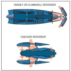
[Figure 15-19 Thrust reversers]
Target reversers are simple clamshell doors that swivel from the stowed position at the engine tailpipe to block all of the outflow and redirect some component of the thrust forward.
Cascade reversers are more complex. They are normally found on turbofan engines and are often designed to reverse only the fan air portion. Blocking doors in the shroud obstructs forward fan thrust and redirects it through cascade vanes for some reverse component. Cascades are generally less effective than target reversers, particularly those that reverse only fan air, because they do not affect the engine core, which will continue to produce forward thrust.
On most installations, reverse thrust is obtained with the thrust lever at idle, by pulling up the reverse lever to a detent. Doing so positions the reversing mechanisms for operation but leaves the engine at idle r.p.m. Further upward and backward movement of the reverse lever increases engine power. Reverse is cancelled by closing the reverse lever to the idle reverse position, then dropping it fully back to the forward idle position. This last movement operates the reverser back to the forward thrust position.
Reverse thrust is much more effective at high airplane speed than at low airplane speeds, for two reasons: first, the net amount of reverse thrust increases with speed; second, the power produced is higher at higher speeds because of the increased rate of doing work. In other words, the kinetic energy of the airplane is being destroyed at a higher rate at the higher speeds. To get maximum efficiency from reverse thrust, therefore, it should be used as soon as is prudent after touchdown.
When considering the proper time to apply reverse thrust after touchdown, the pilot should remember that some airplanes tend to pitch noseup when reverse is selected on landing and this effect, particularly when combined with the noseup pitch effect from the spoilers, can cause the airplane to leave the ground again momentarily. On these types, the airplane must be firmly on the ground with the nosewheel down, before reverse is selected. Other types of airplanes have no change in pitch, and reverse idle may be selected after the main gear is down and before the nosewheel is down. Specific procedures for reverse thrust operation for a particular airplane/engine combination are contained in the FAA-approved Airplane Flight Manual for that airplane.
There is a significant difference between reverse pitch on a propeller and reverse thrust on a jet. Idle reverse on a propeller produces about 60 percent of the reverse thrust available at full power reverse and is therefore very effective at this setting when full reverse is not needed. On a jet engine, however, selecting idle reverse produces very little actual reverse thrust. In a jet airplane, the pilot must not only select reverse as soon as reasonable, but then must open up to full power reverse as soon as possible. Within Airplane Flight Manual limitations, full power reverse should be held until the pilot is certain the landing roll will be contained within the distance available.
Inadvertent deployment of thrust reversers is a very serious emergency situation. Therefore, thrust reverser systems are designed with this prospect in mind. The systems normally contain several lock systems: one to keep reversers from operating in the air, another to prevent operation with the thrust levers out of the idle detent, and/or an “auto-stow” circuit to command reverser stowage any time unwanted motion is detected. It is essential that pilots understand not only the normal procedures and limitations of thrust reverser use, but also the procedures for coping with uncommanded reverse. Those emergencies demand immediate and accurate response.
PILOT SENSATIONS IN JET FLYING
There are usually three general sensations that the pilot transitioning into jets will immediately become aware of. These are: inertial response differences, increased control sensitivity, and a much increased tempo of flight.
The varying of power settings from flight idle to full takeoff power has a much slower effect on the change of airspeed in the jet airplane. This is commonly called lead and lag, and is as much a result of the extremely clean aerodynamic design of the airplane as it is the slower response of the engine.
The lack of propeller effect is also responsible for the lower drag increment at the reduced power settings and results in other changes that the pilot will have to become accustomed to. These include the lack of effective slipstream over the lifting surfaces and control surfaces, and lack of propeller torque effect.
The aft mounted engines will cause a different reaction to power application and may result in a slightly nosedown pitching tendency with the application of power. On the other hand, power reduction will not cause the nose of the airplane to drop to the same extent the pilot is used to in a propeller airplane. Although neither of these characteristics are radical enough to cause transitioning pilots much of a problem, they must be compensated for.
Power settings required to attain a given performance are almost impossible to memorize in the jets, and the pilot who feels the necessity for having an array of power settings for all occasions will initially feel at a loss. The only way to answer the question of “how much power is needed?” is by saying, “whatever is required to get the job done.” The primary reason that power settings vary so much is because of the great changes in weight as fuel is consumed during the flight. Therefore, the pilot will have to learn to use power as needed to achieve the desired performance. In time the pilot will find that the only reference to power instruments will be that required to keep from exceeding limits of maximum power settings or to synchronize r.p.m.
Proper power management is one of the initial problem areas encountered by the pilot transitioning into jet airplanes. Although smooth power applications are still the rule, the pilot will be aware that a greater physical movement of the power levers is required as compared to throttle movement in the piston engines. The pilot will also have to learn to anticipate and lead the power changes more than in the past and must keep in mind that the last 30 percent of engine r.p.m. represents the majority of the engine thrust, and below that the application of power has very little effect. In slowing the airplane, power reduction must be made sooner because there is no longer any propeller drag and the pilot should anticipate the need for drag devices.
Control sensitivity will differ between various airplanes, but in all cases, the pilot will find that they are more sensitive to any change in control displacement, particularly pitch control, than are the conventional propeller airplanes. Because of the higher speeds flown, the control surfaces are more effective and a variation of just a few degrees in pitch attitude in a jet can result in over twice the rate of altitude change that would be experienced in a slower airplane. The sensitive pitch control in jet airplanes is one of the first flight differences that the pilot will notice. Invariably the pilot will have a tendency to over-control pitch during initial training flights. The importance of accurate and smooth control cannot be overemphasized, however, and it is one of the first techniques the transitioning pilot must master.
The pilot of a sweptwing jet airplane will soon become adjusted to the fact that it is necessary and normal to fly at higher angles of attack. It is not unusual to have about 5° of noseup pitch on an approach to a landing. During an approach to a stall at constant altitude, the noseup angle may be as high as 15° to 20°. The higher deck angles (pitch angle relative to the ground) on takeoff, which may be as high as 15°, will also take some getting used to, although this is not the actual angle of attack relative to the airflow over the wing.
The greater variation of pitch attitudes flown in a jet airplane are a result of the greater thrust available and the flight characteristics of the low aspect ratio and sweptwing. Flight at the higher pitch attitudes requires a greater reliance on the flight instruments for airplane control since there is not much in the way of a useful horizon or other outside reference to be seen. Because of the high rates of climb and descent, high airspeeds, high altitudes and variety of attitudes flown, the jet airplane can only be precisely flown by applying proficient instrument flight techniques. Proficiency in attitude instrument flying, therefore, is essential to successful transition to jet airplane flying.
Most jet airplanes are equipped with a thumb operated pitch trim button on the control wheel which the pilot must become familiar with as soon as possible. The jet airplane will differ regarding pitch tendencies with the lowering of flaps, landing gear, and drag devices. With experience, the jet airplane pilot will learn to anticipate the amount of pitch change required for a particular operation. The usual method of operating the trim button is to apply several small, intermittent applications of trim in the direction desired rather than holding the trim button for longer periods of time which can lead to over-controlling.
JET AIRPLANE TAKEOFF AND CLIMB
All FAAcertificated jet airplanes are certificated under Title 14 of the Code of Federal Regulations (14 CFR) part 25, which contains the airworthiness standards for transport category airplanes. The FAA certificated jet airplane is a highly sophisticated machine with proven levels of performance and guaranteed safety margins. The jet airplane’s performance and safety margins can only be realized, however, if the airplane is operated in strict compliance with the procedures and limitations contained in the FAA-approved Airplane Flight Manual for the particular airplane.
The following information is generic in nature and, since most civilian jet airplanes require a minimum flight crew of two pilots, assumes a two pilot crew. If any of the following information conflicts with FAAapproved Airplane Flight Manual procedures for a particular airplane, the Airplane Flight Manual procedures take precedence. Also, if any of the following procedures differ from the FAA-approved procedures developed for use by a specific air operator and/or for use in an FAA-approved training center or pilot school curriculum, the FAA-approved procedures for that operator and/or training center/pilot school take precedence.
V-SPEEDS
The following are speeds that will affect the jet airplane’s takeoff performance. The jet airplane pilot must be thoroughly familiar with each of these speeds and how they are used in the planning of the takeoff.
• VS— Stall speed.
• V1— Critical engine failure speed or decision speed. Engine failure below this speed should result in an aborted takeoff; above this speed the takeoff run should be continued.
• VR—Speed at which the rotation of the airplane is initiated to takeoff attitude. This speed cannot be less than V1 or less than 1.05 x VMCA (minimum control speed in the air). On a single-engine takeoff, it must also allow for the acceleration to V2 at the 35-foot height at the end of the runway.
• VLO—The speed at which the airplane first becomes airborne. This is an engineering term used when the airplane is certificated and must meet certain requirements. If it is not listed in the Airplane Flight Manual, it is within requirements and does not have to be taken into consideration by the pilot.
• V2—The takeoff safety speed which must be attained at the 35-foot height at the end of the required runway distance. This is essentially the best single-engine angle of climb speed for the airplane and should be held until clearing obstacles after takeoff, or at least 400 feet above the ground.
PRE-TAKEOFF PROCEDURES
Takeoff data, including V1/VR and V2 speeds, takeoff power settings, and required field length should be computed prior to each takeoff and recorded on a takeoff data card. These data will be based on airplane weight, runway length available, runway gradient, field temperature, field barometric pressure, wind, icing conditions, and runway condition. Both pilots should separately compute the takeoff data and cross-check in the cockpit with the takeoff data card.
A captain’s briefing is an essential part of cockpit resource management (CRM) procedures and should be accomplished just prior to takeoff.

[Figure 15-20 Sample captain’s briefing.]
The captain’s briefing is an opportunity to review crew coordination procedures for takeoff, which is always the most critical portion of a flight. The takeoff and climb-out should be accomplished in accordance with a standard takeoff and departure profile developed for the particular make and model airplane.
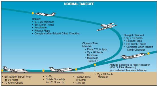
[Figure 15-21 Takeoff and departure profile]
TAKEOFF ROLL
The entire runway length should be available for takeoff, especially if the pre-calculated takeoff performance shows the airplane to be limited by runway length or obstacles. After taxing into position at the end of the runway, the airplane should be aligned in the center of the runway allowing equal distance on either side. The brakes should be held while the thrust levers are brought to a power setting beyond the bleed valve range (normally the vertical position) and the engines allowed to stabilized. The engine instruments should be checked for proper operation before the brakes are released or the power increased further. This procedure assures symmetrical thrust during the takeoff roll and aids in preventing overshooting the desired takeoff thrust setting. The brakes should then be released and, during the start of the takeoff roll, the thrust levers smoothly advanced to the pre-computed takeoff power setting. All final takeoff thrust adjustments should be made prior to reaching 60 knots. The final engine power adjustments are normally made by the pilot not flying. Once the thrust levers are set for takeoff power, they should not be readjusted after 60 knots. Retarding a thrust lever would only be necessary in case an engine exceeds any limitation such as ITT, fan, or turbine r.p.m.
CAPTAIN'S BRIEFING
I will advance the thrust levers.
Follow me through on the thrust levers.
Monitor all instruments and warning lights on the takeoff roll and call out any discrepancies or malfunctions observed prior to V1, and I will abort the takeoff. Stand by to arm thrust reversers on my command.
Give me a visual and oral signal for the following:
• 80 knots, and I will disengage nosewheel steering.
• V1, and I will move my hand from thrust to yoke.
• VR, and I will rotate. In the event of engine failure at or after V1, I will continue the takeoff roll to VR, rotate and establish V2 climb speed. I will identify the inoperative engine, and we will both verify. I will accomplish the shutdown, or have you do it on my command.
I will expect you to stand by on the appropriate emergency checklist.
I will give you a visual and oral signal for gear retraction and for power settings after the takeoff. Our VFR emergency procedure is to.............................
Our IFR emergency procedure is to..............................
Figure 15-20. Sample captain’s briefing.
If sufficient runway length is available, a “rolling” takeoff may be made without stopping at the end of the runway. Using this procedure, as the airplane rolls onto the runway, the thrust levers should be smoothly advanced to the vertical position and the engines allowed to stabilize, and then proceed as in the static takeoff outlined above. Rolling takeoffs can also be made from the end of the runway by advancing the thrust levers from idle as the brakes are released.
During the takeoff roll, the pilot flying should concentrate on directional control of the airplane. This is made somewhat easier because there is no torqueproduced yawing in a jet as there is in a propeller driven airplane. The airplane must be maintained exactly on centerline with the wings level. This will automatically aid the pilot when contending with an engine failure. If a crosswind exists, the wings should be kept level by displacing the control wheel into the crosswind. During the takeoff roll, the primary responsibility of the pilot not flying is to closely monitor the aircraft systems and to call out the proper V speeds as directed in the captain’s briefing.
Slight forward pressure should be held on the control column to keep the nosewheel rolling firmly on the runway. If nosewheel steering is being utilized, the pilot flying should monitor the nosewheel steering to about 80 knots (or VMCG for the particular airplane) while the pilot not flying applies the forward pressure. After reaching VMCG, the pilot flying should bring his/her left hand up to the control wheel.
The pilot’s other hand should be on the thrust levers until at least V1 speed is attained. Although the pilot not flying maintains a check on the engine instruments throughout the takeoff roll, the pilot flying (pilot in command) makes the decision to continue or reject a takeoff for any reason. A decision to reject a takeoff will require immediate retarding of thrust levers. The pilot not flying should call out V1. After passing V1 speed on the takeoff roll, it is no longer mandatory for the pilot flying to keep a hand on the thrust levers. The point for abort has passed, and both hands may be placed on the control wheel. As the airspeed approaches VR, the control column should be moved to a neutral position. As the pre-computed VR speed is attained, the pilot not flying should make the appropriate callout and the pilot flying should smoothly rotate the airplane to the appropriate takeoff pitch attitude.
ROTATION AND LIFT-OFF
Rotation and lift-off in a jet airplane should be considered a maneuver unto itself. It requires planning, precision, and a fine control touch. The objective is to initiate the rotation to takeoff pitch attitude exactly at VR so that the airplane will accelerate through VLOF and attain V2 speed at 35 feet at the end of the runway. Rotation to the proper takeoff attitude too soon may extend the takeoff roll or cause an early lift-off, which will result in a lower rate of climb, and the predicted flightpath will not be followed. A late rotation, on the other hand, will result in a longer takeoff roll, exceeding V2 speed, and a takeoff and climb path below the predicted path.
Each airplane has its own specific takeoff pitch attitude which remains constant regardless of weight. The takeoff pitch attitude in a jet airplane is normally between 10° and 15° nose up. The rotation to takeoff pitch attitude should be made smoothly but deliberately, and at a constant rate. Depending on the particular airplane, the pilot should plan on a rate of pitch attitude increase of approximately 2.5° to 3° per second.
In training it is common for the pilot to overshoot VR and then overshoot V2 because the pilot not flying will call for rotation at, or just past VR. The reaction of the pilot flying is to visually verify VR and then rotate. The airplane then leaves the ground at or above V2. The excess airspeed may be of little concern on a normal takeoff, but a delayed rotation can be critical when runway length or obstacle clearance is limited. It should be remembered that on some airplanes, the all-engine takeoff can be more limiting than the engine out takeoff in terms of obstacle clearance in the initial part of the climb-out. This is because of the rapidly increasing airspeed causing the achieved flightpath to fall below the engine out scheduled flightpath unless care is taken to fly the correct speeds. The transitioning pilot should remember that rotation at the right speed and rate to the right attitude will get the airplane off the ground at the right speed and within the right distance.
INITIAL CLIMB
Once the proper pitch attitude is attained, it must be maintained. The initial climb after lift-off is done at this constant pitch attitude. Takeoff power is maintained and the airspeed allowed to accelerate. Landing gear retraction should be accomplished after a positive rate of climb has been established and confirmed. Remember that in some airplanes gear retraction may temporarily increase the airplane drag while landing gear doors open. Premature gear retraction may cause the airplane to settle back towards the runway surface. Remember also that because of ground effect, the vertical speed indicator and the altimeter may not show a positive climb until the airplane is 35 to 50 feet above the runway.
The climb pitch attitude should continue to be held and the airplane allowed to accelerate to flap retraction speed. However, the flaps should not be retracted until obstruction clearance altitude or 400 feet AGL has been passed. Ground effect and landing gear drag reduction results in rapid acceleration during this phase of the takeoff and climb. Airspeed, altitude, climb rate, attitude, and heading must be monitored carefully. When the airplane settles down to a steady climb, longitudinal stick forces can be trimmed out. If a turn must be made during this phase of flight, no more than 15° to 20° of bank should be used. Because of spiral instability, and because at this point an accurate trim state on rudder and ailerons has not yet been achieved, the bank angle should be carefully monitored throughout the turn. If a power reduction must be made, pitch attitude should be reduced simultaneously and the airplane monitored carefully so as to preclude entry into an inadvertent descent. When the airplane has attained a steady climb at the appropriate en route climb speed, it can be trimmed about all axes and the autopilot engaged.
JET AIRPLANE APPROACH AND LANDING LANDING REQUIREMENTS
The FAA landing field length requirements for jet airplanes are specified in 14 CFR part 25. It defines the minimum field length (and therefore minimum margins) that can be scheduled. The regulation describes the landing profile as the distance required from a point 50 feet above the runway threshold, through the flare to touchdown, and then stopping using the maximum stopping capability on a dry runway surface. The actual demonstrated distance is increased by 67 percent and published in the FAAapproved Airplane Flight Manual as the FAR dry runway landing distance.
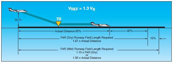
[Figure 15-22 FAR landing field length required]
For wet runways, the FAR dry runway distance is increased by an additional 15 percent. Thus the minimum dry runway field length will be 1.67 times the actual minimum air and ground distance needed and the wet runway minimum landing field length will be 1.92 times the minimum dry air and ground distance needed.
Certified landing field length requirements are computed for the stop made with speed brakes deployed and maximum wheel braking. Reverse thrust is not used in establishing the certified FAR landing distances. However, reversers should definitely be used in service.
LANDING SPEEDS
As in the takeoff planning, there are certain speeds that must be taken into consideration during any landing in a jet airplane. The speeds are as follows.
• VSO—Stall speed in the landing configuration.
• VREF—1.3 times the stall speed in the landing configuration.
• Approach climb—The speed which guarantees adequate performance in a go-around situation with an inoperative engine. The airplane’s weight must be limited so that a twin-engine airplane will have a 2.1 percent climb gradient capability. (The approach climb gradient requirements for 3 and 4 engine airplanes are 2.4 percent and 2.7 percent respectively.) These criteria are based on an airplane configured with approach flaps, landing gear up, and takeoff thrust available from the operative engine(s).
• Landing climb—The speed which guarantees adequate performance in arresting the descent and making a go-around from the final stages of landing with the airplane in the full landing configuration and maximum takeoff power available on all engines. The appropriate speeds should be pre-computed prior to every landing, and posted where they are visible to both pilots. The VREF speed, or threshold speed, is used as a reference speed throughout the traffic pattern. For example:
Downwind leg—VREF plus 20 knots.
Base leg—VREF plus 10 knots.
Final approach—VREF plus 5 knots. 50 feet over threshold—VREF.
The approach and landing sequence in a jet airplane should be accomplished in accordance with an approach and landing profile developed for the particular airplane.
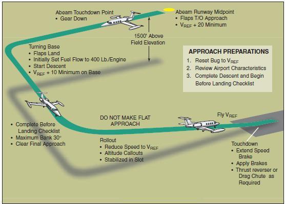
[Figure 15-23 Typical approach and landing profile]
SIGNIFICANT DIFFERENCES
Asafe approach in any type of airplane culminates in a particular position, speed, and height over the runway threshold. That final flight condition is the target window at which the entire approach aims. Propeller powered airplanes are able to approach that target from wider angles, greater speed differentials, and a larger variety of glidepath angles. Jet airplanes are not as responsive to power and course corrections, so the final approach must be more stable, more deliberate, more constant, in order to reach the window accurately. The transitioning pilot must understand that, in spite of their impressive performance capabilities, there are six ways in which a jet airplane is worse than a piston engine airplane in making an approach and in correcting errors on the approach.
• The absence of the propeller slipstream in producing immediate extra lift at constant airspeed. There is no such thing as salvaging a misjudged glidepath with a sudden burst of immediately available power. Added lift can only be achieved by accelerating the airframe. Not only must the pilot wait for added power but even when the engines do respond, added lift will only be available when the airframe has responded with speed.
• The absence of the propeller slipstream in significantly lowering the power-on stall speed. There is virtually no difference between poweron and power-off stall speed. It is not possible in a jet airplane to jam the thrust levers forward to avoid a stall.
• Poor acceleration response in a jet engine from low r.p.m. This characteristic requires that the approach be flown in a high drag/high power configuration so that sufficient power will be available quickly if needed.
• The increased momentum of the jet airplane making sudden changes in the flightpath impossible. Jet airplanes are consistently heavier than comparable sized propeller airplanes. The jet airplane, therefore, will require more indicated airspeed during the final approach due to a wing design that is optimized for higher speeds. These two factors combine to produce higher momentum for the jet airplane. Since force is required to overcome momentum for speed changes or course corrections, the jet will be far less responsive than the propeller airplane and require careful planning and stable conditions throughout the approach.
• The lack of good speed stability being an inducement to a low speed condition. The drag curve for many jet airplanes is much flatter than for propeller airplanes, so speed changes do not produce nearly as much drag change. Further, jet thrust remains nearly constant with small speed changes. The result is far less speed stability. When the speed does increase or decrease, there is little tendency for the jet airplane to re-acquire the original speed. The pilot, therefore, must remain alert to the necessity of making speed adjustments, and then make them aggressively in order to remain on speed.
• Drag increasing faster than lift producing a high sink rate at low speeds. Jet airplane wings typically have a large increase in drag in the approach configuration. When a sink rate does develop, the only immediate remedy is to increase pitch attitude (angle of attack). Because drag increases faster than lift, that pitch change will rapidly contribute to an even greater sink rate unless a significant amount of power is aggressively applied. These flying characteristics of jet airplanes make a stabilized approach an absolute necessity.
THE STABILIZED APPROACH
The performance charts and the limitations contained in the FAA-approved Airplane Flight Manual are predicated on momentum values that result from programmed speeds and weights. Runway length limitations assume an exact 50-foot threshold height at an exact speed of 1.3 times VSO. That “window” is critical and is a prime reason for the stabilized approach. Performance figures also assume that once through the target threshold window, the airplane will touch down in a target touchdown zone approximately 1,000 feet down the runway, after which maximum stopping capability will be used. There are five basic elements to the stabilized approach.
• The airplane should be in the landing configuration early in the approach. The landing gear should be down, landing flaps selected, trim set, and fuel balanced. Ensuring that these tasks are completed will help keep the number of variables to a minimum during the final approach.
• The airplane should be on profile before descending below 1,000 feet. Configuration, trim, speed, and glidepath should be at or near the optimum parameters early in the approach to avoid distractions and conflicts as the airplane nears the threshold window. An optimum glidepath angle of 2.5° to 3° should be established and maintained.
• Indicated airspeed should be within 10 knots of the target airspeed. There are strong relationships between trim, speed, and power in most jet airplanes and it is important to stabilize the speed in order to minimize those other variables.
• The optimum descent rate should be 500 to 700 feet per minute. The descent rate should not be allowed to exceed 1,000 feet per minute at any time during the approach.
• The engine speed should be at an r.p.m. that allows best response when and if a rapid power increase is needed. Every approach should be evaluated at 500 feet. In a typical jet airplane, this is approximately 1 minute from touchdown. If the approach is not stabilized at that height, a go-around should be initiated.
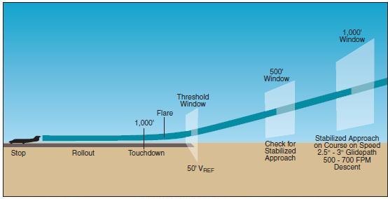
[Figure 15-24 Stabilized approach]
APPROACH SPEED
On final approach, the airspeed is controlled with power. Any speed diversion from VREF on final approach must be detected immediately and corrected. With experience the pilot will be able to detect the very first tendency of an increasing or decreasing airspeed trend, which normally can be corrected with a small adjustment in thrust. The pilot must be attentive to poor speed stability leading to a low speed condition with its attendant risk of high drag increasing the sink rate. Remember that with an increasing sink rate an apparently normal pitch attitude is no guarantee of a normal angle of attack value. If an increasing sink rate is detected, it must be countered by increasing the angle of attack and simultaneously increasing thrust to counter the extra drag. The degree of correction required will depend on how much the sink rate needs to be reduced. For small amounts, smooth and gentle, almost anticipatory corrections will be sufficient. For large sink rates, drastic corrective measures may be required that, even if successful, would destabilize the approach.
A common error in the performance of approaches in jet airplanes is excess approach speed. Excess approach speed carried through the threshold window and onto the runway will increase the minimum stopping distance required by 20 – 30 feet per knot of excess speed for a dry runway and 40 – 50 feet for a wet runway. Worse yet, the excess speed will increase the chances of an extended flare, which will increase the distance to touchdown by approximately 250 feet for each excess knot in speed.
Proper speed control on final approach is of primary importance. The pilot must anticipate the need for speed adjustment so that only small adjustments are required. It is essential that the airplane arrive at the approach threshold window exactly on speed.
GLIDEPATH CONTROL
On final approach, at a constant airspeed, the glidepath angle and rate of descent is controlled with pitch attitude and elevator. The optimum glidepath angle is 2.5° to 3° whether or not an electronic glidepath reference is being used. On visual approaches, pilots may have a tendency to make flat approaches. A flat approach, however, will increase landing distance and should be avoided. For example, an approach angle of 2° instead of a recommended 3° will add 500 feet to landing distance.
A more common error is excessive height over the threshold. This could be the result of an unstable approach, or a stable but high approach. It also may occur during an instrument approach where the missed approach point is close to or at the runway threshold. Regardless of the cause, excessive height over the threshold will most likely result in a touchdown beyond the normal aiming point. An extra 50 feet of height over the threshold will add approximately 1,000 feet to the landing distance. It is essential that the airplane arrive at the approach threshold window exactly on altitude (50 feet above the runway).
THE FLARE
The flare reduces the approach rate of descent to a more acceptable rate for touchdown. Unlike light airplanes, a jet airplane should be flown onto the runway rather than “held off” the surface as speed dissipates. A jet airplane is aerodynamically clean even in the landing configuration, and its engines still produce residual thrust at idle r.p.m. Holding it off during the flare in a attempt to make a smooth landing will greatly increase landing distance. A firm landing is normal and desirable. A firm landing does not mean a hard landing, but rather a deliberate or positive landing.
For most airports, the airplane will pass over the end of the runway with the landing gear 30 – 45 feet above the surface, depending on the landing flap setting and the location of the touchdown zone. It will take 5 – 7 seconds from the time the airplane passes the end of the runway until touchdown. The flare is initiated by increasing the pitch attitude just enough to reduce the sink rate to 100 – 200 feet per minute when the landing gear is approximately 15 feet above the runway surface. In most jet airplanes, this will require a pitch attitude increase of only 1° to 3°. The thrust is smoothly reduced to idle as the flare progresses.
The normal speed bleed off during the time between passing the end of the runway and touchdown is 5 knots. Most of the decrease occurs during the flare when thrust is reduced. If the flare is extended (held off) while an additional speed is bled off, hundreds or even thousands of feet of runway may be used up.
[Figure 15-25 Extended flare.]
The extended flare will also result in additional pitch attitude which may lead to a tail strike. It is, therefore, essential to fly the airplane onto the runway at the target touchdown point, even if the speed is excessive. A deliberate touchdown should be planned and practiced on every flight. A positive touchdown will help prevent an extended flare. Pilots must learn the flare characteristics of each model of airplane they fly. The visual reference cues observed from each cockpit are different because window geometry and visibility are different. The geometric relationship between the pilot’s eye and the landing gear will be different for each make and model. It is essential that the flare maneuver be initiated at the proper height—not too high and not too low. Beginning the flare too high or reducing the thrust too early may result in the airplane floating beyond the target touchdown point or may include a rapid pitch up as the pilot attempts to prevent a high sink rate touchdown. This can lead to a tail strike. The flare that is initiated too late may result in a hard touchdown. Proper thrust management through the flare is also important. In many jet airplanes, the engines produce a noticeable effect on pitch trim when the thrust setting is changed. Arapid change in the thrust setting requires a quick elevator response. If the thrust levers are moved to idle too quickly during the flare, the pilot must make rapid changes in pitch control. If the thrust levers are moved more slowly, the elevator input can be more easily coordinated. Touchdown On Target Extended Flare 10 Knots Deceleration on Ground (Maximum Braking) 10 Knots Deceleration in Flare 200 Ft. (Dry Runway) 500 Ft. (Wet Runway) 2,000 Ft. (Air) Figure 15-25. Extended flare.
TOUCHDOWN AND ROLLOUT
A proper approach and flare positions the airplane to touch down in the touchdown target zone, which is usually about 1,000 feet beyond the runway threshold. Once the main wheels have contacted the runway, the pilot must maintain directional control and initiate the stopping process. The stop must be made on the runway that remains in front of the airplane. The runway distance available to stop is longest if the touchdown was on target. The energy to be dissipated is least if there is no excess speed. The stop that begins with a touchdown that is on the numbers will be the easiest stop to make for any set of conditions. At the point of touchdown, the airplane represents a very large mass that is moving at a relatively high speed. The large total energy must be dissipated by the brakes, the aerodynamic drag, and the thrust reversers. The nosewheel should be flown onto the ground immediately after touchdown because a jet airplane decelerates poorly when held in a nose-high attitude. Placing the nosewheel tire(s) on the ground will assist in maintaining directional control. Also, lowering the nose gear decreases the wing angle of attack, decreasing the lift, placing more load onto the tires, thereby increasing tire-to-ground friction. Landing distance charts for jet airplanes assume that the nosewheel is lowered onto the runway within 4 seconds of touchdown. There are only three forces available for stopping the airplane. They are wheel braking, reverse thrust, and aerodynamic braking. Of the three, the brakes are most effective and therefore the most important stopping force for most landings. When the runway is very slippery, reverse thrust and drag may be the dominant forces. Both reverse thrust and aerodynamic drag are most effective at high speeds. Neither is affected by runway surface condition. Brakes, on the other hand, are most effective at low speed. The landing rollout distance will depend on the touchdown speed and what forces are applied and when they are applied. The pilot controls the what and when factors, but the maximum braking force may be limited by tire-to-ground friction. The pilot should begin braking as soon after touchdown and wheel spin-up as possible, and to smoothly continue the braking until stopped or a safe taxi speed is reached. However, caution should be used if the airplane is not equipped with a functioning anti-skid system. In such a case, heavy braking can cause the wheels to lock and the tires to skid. Both directional control and braking utilize tire ground friction. They share the maximum friction force the tires can provide. Increasing either will subtract from the other. Understanding tire ground friction, how runway contamination affects it, and how to use the friction available to maximum advantage is important to a jet pilot. Spoilers should be deployed immediately after touchdown because they are most effective at high speed. Timely deployment of spoilers will increase drag by 50 to 60 percent, but more importantly, they spoil much of the lift the wing is creating, thereby causing more of the weight of the airplane to be loaded onto the wheels. The spoilers increase wheel loading by as much as 200 percent in the landing flap configuration. This increases the tire ground friction force making the maximum tire braking and cornering forces available. Like spoilers, thrust reversers are most effective at high speeds and should be deployed quickly after touchdown. However, the pilot should not command significant reverse thrust until the nosewheel is on the ground. Otherwise, the reversers might deploy asymmetrically resulting in an uncontrollable yaw towards the side on which the most reverse thrust is being developed, in which case the pilot will need whatever nosewheel steering is available to maintain directional control.
Selected Knowledge field from the left to find out more about knowledge related to Pilot Training.
Click here to get a complete list of Aircraft Schools the entire United States.
Copyright © 2008 AirplaneGroundSchools.com | All Rights Reserved
Design G. Wolfgang | W3C XHTML 1.0 | W3C CSS 2.0
Courtesy Open Web Design![]() Thanks to Florida Vacation Homes
Thanks to Florida Vacation Homes