Airplane Ground Schools
Knowledge of Flying is Our passion.
Serving the General Aviation Community
|
|
Introduction
This chapter introduces the topic of navigation in the advanced cockpit. You will learn about flight management systems (FMS) and area navigation (RNAV) systems, an increasingly popular method of navigating that allows pilots to make more efficient use of the national airspace system. The increasing number of users is attributable to more economical and accurate satellite signal receivers and computer chips. RNAV systems may use VHF omnidirectional range (VOR); distance measuring equipment (DME) (VOR/DME, DME/DME) signals; inertial navigation systems (INS); Doppler radar; the current version of LOng RAnge Navigation (LORAN), LORAN-C (and eLORAN, as it becomes operational); and the global positioning system (GPS), to name a few. Ground-based LORAN-C is a reliable complement to spacebased GPS systems (United States Department of Defense (DOD) GPS, Russian Global Navigation Satellite System (GLONASS), and European Galileo in the future).
Navigation Chapter Wide area augmentation system (WAAS) of the standard GPS furnishes additional error correction information, allowing Category I precision approaches (similar to basic instrument landing system (ILS) minimums) to units equipped to receive and integrate the data. Most general aviation pilots learn to work with an FMS unit primarily using GPS signals, possibly with WAAS and LORAN-C options. Older RNAV units made use of VOR and DME information to compute positions within range of the navaids. Newer units contain databases that allow route programming with automatic sequencing through the selected navigation points. Therefore, flight management system (FMS) is the best descriptor of the current GPS units integrating VOR (and DME, optionally) to allow point-to-point navigation outside established flight routes. You will learn to use the FMS data entry controls to program a flight route, review the planned route, track and make modifications to the planned route while en route, plan and execute a descent, and fly an approach procedure that is based solely on RNAV signals. You should remember that FMS/RNAV units requiring external signals for navigation are usually restricted to line-of-sight reception (LORAN-C being somewhat of an exception). Therefore, navigation information in valleys and canyons that could block satellite signals may be severely restricted. Users in those areas should pay particular attention to the altitude or elevations of the satellites when depending on space-based signals and plan flight altitudes to ensure line-of-sight signal reception. Review the GPS unit’s documentation sufficiently to determine if WAAS is installed and how WAAS corrections are indicated.
You will learn how the FMS can automatically perform many of the flight planning calculations that were traditionally performed by hand, and the importance of keeping flight planning skills fresh. You will also discover how the FMS can help you detect and correct errors made in the flight planning process, how the complexities of the FMS make some new kinds of errors possible, and techniques to help avoid them.
Last, you will see how advanced cockpit systems can be used to navigate using ground-based navigation facilities such as VOR and DME. Maintaining pilot skills using ground-based navigation facilities is a simple matter of occasionally using them as the primary means of navigation, and as a backup to verify position and progress when RNAV is used.
Area Navigation (RNAV) Basics
RNAV Concept
Area Navigation (RNAV) is a navigation technique that allows pilots to navigate directly between any two points on the globe. Using RNAV, any location on the map can be defined in terms of latitude and longitude and characterized as a waypoint. Onboard RNAV equipment can determine the present position of the aircraft. Using this positional information, the equipment can calculate the bearing and distance to or from any waypoint and permit navigation directly between any two waypoints. In this way, RNAV overcomes a fundamental limitation of conventional navaid point-to-point navigation techniques, which require navigating between electronic navigation transmitters on the ground. The following examples illustrate this limitation.
An aircraft equipped with conventional VOR receivers is positioned at Point A as shown in the diagram at the top of Figure 3-1, and the pilot wishes to navigate directly to Point B. Although there appear to be a few VOR stations in the vicinity of the aircraft, it is not clear whether reception is possible from the aircraft’s present position. If the VOR stations are within reception range, the pilot has two choices:
(1) fly to intercept the closest airway, then track it to the intersection; or
(2) fly to intercept an extension of the radial that defines Point B (assuming reception is possible).
Neither alternative provides the pilot with a means of flying directly to the intersection.
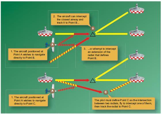
Figure 3-1. Limitations of conventional navigation
Suppose the same aircraft is positioned at Point A as shown at the bottom of Figure 3-1 and the pilot wishes to navigate directly to Point C, which is neither a VOR station nor airway intersection. This pilot has an even more difficult situation. Assuming the VOR stations are within reception range, the pilot needs to create two makeshift airways using a navigation plotter and chart, fly to intercept one of them, then track to Point C (which the pilot has defined as the intersection between the two courses). Flying a direct course to Point C with any degree of accuracy is not possible. Since RNAV systems are not bound by these limitations, the entire airspace is available for navigational use. The national airspace system can thus accommodate more aircraft. However, when the pilot leaves the established airways, he or she also leaves the guaranteed obstruction clearances designed into the airway system. Always plan flights above the maximum elevation figure (MEF) displayed on sectional charts when flying off airways, and be aware that manmade obstructions such as towers may not be added to charts for some time after construction. If flying a new routing, allow for construction, which may not be published yet.
FMS/RNAV Computer
RNAV is possible through use of a variety of navigation facilities and installed aircraft equipment operated in the U.S. National Airspace System. This handbook focuses on the more common GPS RNAV, a satellite-based radio navigation system available to aircraft equipped with a GPS receiver. In addition to its ability to receive signals from GPS satellites, a GPS receiver also contains a computer processor and a navigation database that includes much of the information found on en route and terminal procedure charts. The newer, more capable units provide map displays, traffic and weather overlays of data, contain VOR/DME/localizer/ glideslope receivers, and can compute fuel usage in addition to the navigation route information. For this reason, the more descriptive term “FMS” is used in this handbook to refer to these GPS receivers.
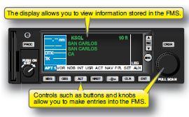
Figure 3-2. FMS display and controls.
An FMS allows you to enter a series of waypoints and instrument procedures that define a flight route. If these waypoints and procedures are included in the navigation database, the computer calculates the distances and courses between all waypoints in the route. During flight, the FMS provides precise guidance between each pair of waypoints in the route, along with real-time information about aircraft course, groundspeed, distance, estimated time between waypoints, fuel consumed, and fuel/flight time remaining (when equipped with fuel sensor(s)).
FMS/RNAV/Autopilot Interface: Display and Controls
Every avionics device has a display and a collection of buttons, keys, and knobs used to operate the unit. The display allows the device(s) to present information. The controls allow the pilot to enter information and program the avionics to accomplish the desired operations or tasks. The display and controls for a typical FMS are shown in Figure 3-2.
Accessing Information in the FMS
FMS units contain much more information than they can present on the display at any one time. Information pertaining to some topics often extends beyond what can be presented on a single page. Page groups, or chapters, solve this problem by collecting all of the pages pertaining to the same topic. Each page presents information about a particular topic, and bears a page title reflecting its content. For example, the airport chapter may be divided into several airport pages, each page displaying different information about that airport. One page might be navaids. Another page might be the airport taxiway diagram. Yet another airport page might indicate available services and fixed-base operators. Review the documentation for that specific unit and installation to determine what information and levels of data are available and require updates. Usually, only one page can be displayed at a time. The airport page is displayed on the FMS in Figure 3-3.
.JPG)
Figure 3-3. Pages and page groups (chapters)
Figure 3-3 shows how to access pages and chapters on one manufacturer’s FMS. Different FMS units have different ways of allowing the pilot to switch between chapters and pages, and different ways of informing the pilot which chapter and page is currently displayed.
Making Entries in the FMS
To enter data, you use the FMS buttons (keyboard or individual) and knob controls, or a data source, such as disk media or keypad, as shown in Figure 3-4.
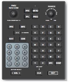
Figure 3-4. An FMS keypad
FMS units that do not feature keypads typically require the pilot to make entries using the same knobs to move among chapters and pages. In this case, the knobs have multiple purposes and, thus, have different modes of operation. To use the knobs for data entry, you must first activate what some manufacturers call the “cursor” (or “data entry”) mode. Activating the cursor mode allows you to enter data by turning the knob. In other units, after activating the data entry mode, entries are made by pushing buttons.
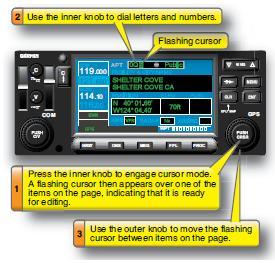
Figure 3-5. Making entries using cursor mode
Figure 3-5 illustrates the use of cursor mode to enter the name of an airport using one FMS. Pressing the inner knob engages cursor mode. A flashing cursor appears over one of the items on the page, indicating that it is ready for editing. Then, the inner knob is used to dial letters and numbers; the outer knob is used to move the flashing cursor between items on the page.
Integrated Avionics Systems
Some systems integrate FMS/RNAV display and controls into existing cockpit displays usually called PFDs and MFDs. In this case, there is no separate display to point to and call the RNAV display. Figure 3-6 shows a system that uses the PFD to provide controls and a display for the FMS. This type of system utilizes the same concepts and procedures described above to access and enter into the navigation computer.
Learning: Simulators for Learning and Practice
Avionics simulators can assist the pilot in developing proficiency in the advanced cockpit. Some manufacturers offer computer-based simulators that run on a personal computer and let the pilot learn how the unit organizes and presents information, as well as practice the button-pushing and knob-twisting procedures needed to access and enter data. One very important function that every pilot of programmable avionics should learn and remember is how to cancel entries and functions. Turbulent flight conditions make data entry errors very easy to make. Every pilot should know how to revert quickly to the basic aircraft controls and functions to effect recovery in times of extreme stress. These programs are extremely useful not only for initial learning, but also for maintaining proficiency. For more sophisticated training, many manufacturers of flight simulators and flight training devices are now developing devices with advanced cockpit systems. These training platforms allow the pilot to work through realistic flying scenarios that teach not only the operating procedures required for each system, but also how to use the systems most effectively.
Flight Planning
Preflight Preparation
Title 14 of the Code of Federal Regulations (14 CFR) part 91, section 91.103 requires you to become familiar with all available information before beginning a flight. In addition to the required checks of weather, fuel, alternate airports, runway lengths, and aircraft performance, there are a number of requirements unique to the use of avionics equipment. Many of these considerations apply specifically to the use of FMS/RNAV under instrument flight rules (IFR). However, a check of these same requirements before operating under visual flight rules (VFR) enhances safety and enforces good habit patterns, which have been proven to greatly enhance aviation safety.
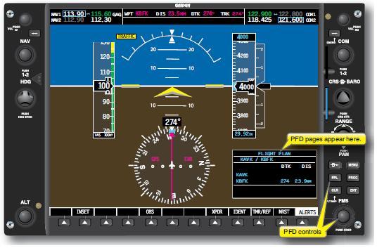
Figure 3-6. An integrated avionics system.
FMS/RNAV Approval for IFR Operations
Only some FMS/RNAV units are approved for IFR navigation, and it is important to make this determination before flying with any particular unit. Sometimes, this limitation is based on the installation (i.e., method of installation, qualifications of installer), aircraft approval, availability of approved maintenance, and geographic location. No hand-held GPS unit is approved for IFR navigation, and many panel-mounted units are restricted to VFR use only. Even when an FMS is approved for IFR, the installation of the system in that specific aircraft must also be approved.
Even if you have an IFR-approved FMS unit, you may not use it for IFR navigation unless the installation is approved as well. This approval process usually requires a test flight to ensure that there are no interfering inputs, signals or static emanating from the aircraft in flight. RNAV units that do not meet all of these requirements may still be used as situation enhancing navigation resources when operating under instrument flight rules.
The first place to check when determining IFR certification for an FMS is the Pilot’s Operating Handbook (POH) or Aircraft Flight Manual (AFM). For every aircraft with an IFR approved FMS/RNAV unit, the AFM explicitly states that the unit has been approved for IFR navigation and what IFR operations are specifically authorized for that installation.
Navigation Database Currency
The navigation database contained in the FMS must be current if the system is to be used for IFR navigation and approaches. Some units allow en route IFR operations if the navigation waypoints are manually verified by the pilot and accepted. The effective dates for the navigation database are shown on a start-up screen that is displayed as the FMS cycles through its startup self-test. Check these dates to ensure that the navigation database is current. Figure 3-7 shows the start-up screen and effective dates for one popular FMS.

Figure 3-7. Checking the navigation database.
Alternative Means of Navigation
To use some GPS-based RNAV units (those certified under Technical Standard Order (TSO) 129) for IFR flight, an aircraft must also be equipped with an approved and alternate means of IFR navigation (e.g., VOR receiver) appropriate to the flight. Ensure that this equipment is onboard and operational, and that all required checks have been performed (e.g., 30-day VOR check). The avionics operations manual/handbook should state the certification status of the installed system. The supplements to the AFM should state the status of the installed equipment, including the installed avionics. Most systems require that the advanced avionics manuals be on board as a limitation of use.
NOTAMs Relevant to GPS
There are numerous notices to airmen (NOTAMs) that apply specifically to users of navigation aids. For example, when anomalies are observed in the behavior of the global positioning system, or when tests are performed, a GPS UNRELIABLE NOTAM is issued. Similarly, published instrument procedures that rely on RNAV equipment sometimes become “Not Available” when safety concerns arise, such as ground-based interference. It is important to check all NOTAMs prior to IFR flights and, especially, GPS and WAAS NOTAMs before flying. Remember, when talking to a flight service station (FSS)/automated flight service station (AFSS) briefer, you must specifically request GPS/WAAS NOTAMs.
GPS Signal Availability
GPS-based RNAV equipment that uses the DOD GPS relies on adequate signal reception throughout the course of a flight. Signal reception becomes especially critical during instrument approaches when signal reception criteria become more stringent. Signal reception is generally predictable, and you can request information on likely signal reception for the destination airport in the preflight briefing from Flight Service. Many GPS RNAV units include a feature called receiver autonomous integrity monitoring (RAIM) that allows you to view predictions about future signal reception at specific locations. WAAS-enabled receivers do not have this restriction or limitation due to the error corrections available from the WAAS. WAAS is a form of differential GPS (DGPS) providing enhanced position accuracy. Each Wide Area Reference Station (WRS) provides correction data to a Wide Area Master Station (WMS), which computes a grid of correction data to be uplinked to a geostationary satellite (GEO) from a Ground Earth Station (GES). The geostationary satellite transmits the correction data (and also navigation data) to the user on the L1 GPS navigation frequency (1575.42 MHz). The user GPS receiver uses the downlink WAAS data to correct received navigation data. The goal of WAAS is to obtain at least a 7-meter horizontal and vertical accuracy.
Local Area Augmentation System (LAAS), when it becomes available, is another DGPS mode which is designed to provide 1-meter accuracy for precision approaches. It uses a local error VHF transmitter near the runway providing a direct link from the sensor to the aircraft GPS receiver.
Alternate Airports
It is very important to know what equipment is installed in the aircraft. GPS-based FMS/RNAV units certified to TSO-C145A or TSO-146A may be used when an alternate airport is required in the flight plan for the approaches at the destination and alternate airport if the WAAS is operational. No other navigation avionics would be required. Units certified under TSO-C129 are not authorized for alternate approach requirements. The aircraft must have stand-alone navigation equipment, such as VOR, and there must be an approved instrument approach at the alternate airport based on that equipment. (However, once diverted to the alternate airport, the pilot could fly a GPS-based approach there, as long as there is an operational, ground-based navaid and airborne receiver in the aircraft for use as a backup.)
Aircraft Equipment Suffixes
Since air traffic control (ATC) issues clearances based on aircraft equipment suffixes, consult the Aeronautical Information Manual (AIM) Table 5-1-2, Aircraft Suffixes, to ensure that the flight plan includes the correct equipment suffix for a particular aircraft. Use the suffix that corresponds to the services and/or routing that is needed. For example, if the desired route or procedure requires GPS, file the suffix as “/G” or “/L,” as appropriate to that aircraft, and operational equipment installed. (Remember that minimum equipment list (MEL) deferred items can change the status of the aircraft.)
Suitability of an RNAV Unit for VFR Flight
Even when an RNAV receiver is to be used only for supplemental (“supplemental” meaning a situation enhancing source of navigation information, but not the primary or sole source of navigation information) navigation information during VFR flight, you should consider these suitability factors in the interest of safety. The use of an expired navigation database might cause you to stray into airspace that was not yet designated at the time the expired navigation database was published. Some VFR-only GPS units do not alert you when signal reception has faded, which could lead to reliance on erroneous position information. Lack of attention to the “see and avoid” basic principle of every visual meteorological conditions (VMC) flight means too much time spent focused inside the cockpit on advanced avionics versus staying synchronized with the flight events, possibly creating a life-threatening total flight situation.
Programming the Flight Route
The procedures used to program an FMS with your intended route of flight are fundamentally the same in all types of systems, yet many differences are evident. The primary difference between systems lies mainly in the “knob or switchology”—the specific design features, operational requirements, and layout of the controls and displays used to operate the avionics. Be thoroughly familiar with the procedures required for each FMS or RNAV unit to be used. Suppose you have planned a flight from San Carlos Airport (KSQL) to Oakdale Airport (O27), as shown in the flight plan appearing in Figure 3-8. The planned route proceeds directly to SUNOL intersection, then follows V195 until reaching ECA, the initial approach fix for the GPS Runway 10 approach into Oakdale. The distances, bearings, estimated times en route, and fuel requirements for the flight have all been calculated. The next step is to enter some of these details into the FMS.
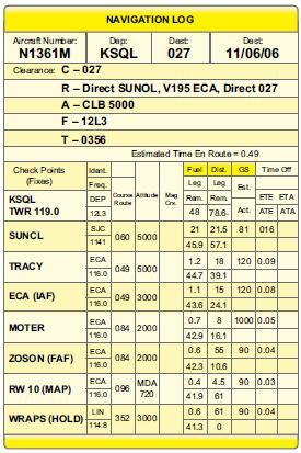
Figure 3-8. A conventional flight plan.
The Flight Planning Page
Every FMS unit includes a page dedicated to entering a flight plan. Typically, entering a flight plan is a simple matter of “filling in the blanks”—entering the en route waypoints and instrument procedures that make up the planned route.
En Route Waypoints and Procedural Waypoints
Entering a flight route into the FMS unit requires you to enter the waypoints that define your route. FMS distinguish between two kinds of waypoints:
(1) waypoints that are published, such as departure, arrival, or approach procedure points; and
(2) user defined waypoints.
The approved system software (the internal programming) allows the pilot to manually enter airport and en route waypoints. However, you are prohibited by the software from entering (or deleting) individual waypoints that define a published instrument procedure, since misspelling a procedural waypoint name or deleting a procedural waypoint (e.g., final approach fix) could have disastrous consequences. Any changes to the selected database approach procedure will cancel the approach mode. Changing to go direct to a waypoint will not, in most units, cancel the approach mode (such as receiving radar vectors to final and bypassing an intermediate fix).
Entering En Route Waypoints
Looking at the planned route in Figure 3-8, it is apparent that San Carlos airport (KSQL), and SUNOL and TRACY intersections are not part of any instrument procedure that pertains to the planned flight. These waypoints can be entered into the unit, as shown in Figure 3-9.
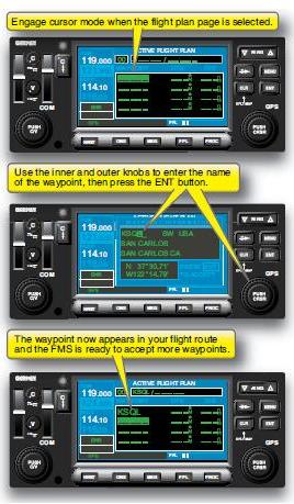
Figure 3-9. Entering en route waypoints in the flight plan
The remaining waypoints in Figure 3-8, starting with the initial approach fix at ECA, are part of the Oakdale GPS approach procedure. Waypoints that are part of a published instrument procedure are entered by a different technique that will be introduced later. In some cases, you navigate along an airway that contains a string of waypoints, such as the one shown in Figure 3-10.

Figure 3-10. Entering waypoints along an airway
In this case, it is only necessary to enter waypoints along the airway that represent course changes. In Figure 3-10, REANS intersection is a changeover point that joins the Pomona 073-degree radial and the Twentynine Palms 254-degree radial. For this airway segment, you could enter POM, REANS, and TNP, keeping in mind that the remaining waypoints do not appear in the programmed route.
Entering Airways
More sophisticated FMSs allow you to enter entire airways with a single action into the unit. When an airway and endpoint for that airway are selected, all waypoints that occur along the airway are automatically inserted into the flight plan.Figure 3-11 shows a navigation unit that allows airways to be selected.
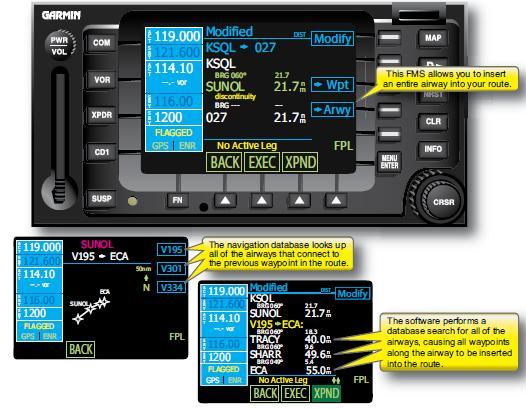
Figure 3-11. Inserting an airway into a flight route
Entering Procedures
Every IFR-capable FMS offers a menu of published instrument procedures, such as departures, arrivals, and approaches. When you choose one of these procedures, the FMS automatically inserts all waypoints included in that procedure into the flight plan. Figure 3-12 illustrates how you might choose an approach procedure using one popular FMS.
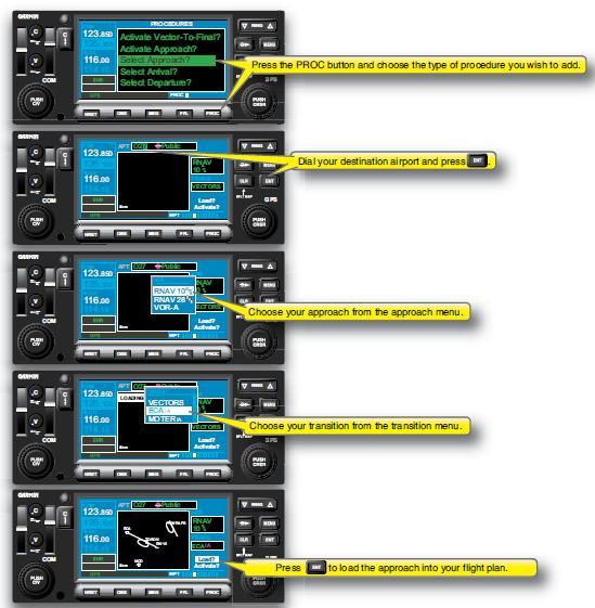
Figure 3-12. Inserting published instrument procedures into a flight route
Risk: Taking Off Without Entering a Flight Plan
The convenience of the FMS, especially the “direct to” feature common to all units, creates the temptation to program only the first en route waypoint prior to takeoff and then enter additional waypoints once airborne. Keep in mind, however, that no matter how skilled you become with the avionics, programming requires “heads down” time, which reduces your ability to scan for traffic, monitor engine instruments, etc. A better strategy is to enter all of the flight data before you take off.
Reviewing the Flight Route
Once a route has been entered into the FMS, the next step is to review the route to ensure it is the desired route. It is particularly important to ensure that the programmed route agrees with the pilot’s clearance, the en route and terminal area charts, and any bearing, distance, time, and fuel calculations that have been performed on paper.
Catching Errors: Using the FMS Flight Planning Function To Cross-Check Calculations
Using the FMS’s flight planning function to check your own flight planning calculations is one example of how advanced cockpit systems can decrease the likelihood of an error. Alternatively, cross-check the computer’s calculations against your own. (Remember the old computer programmer’s adage, “Garbage in, garbage out (GIGO).”)
The flight planning page can also be used to review the route that you entered into the FMS, as illustrated in Figure 3-13. Be sure to check at least four things when reviewing your route.
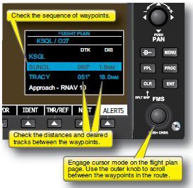
Figure 3-13. Reviewing the flight route
Check the Waypoints
On the flight planning page, compare the sequence of waypoints with that prescribed by his or her clearance. Are any waypoints missing? Did you mistakenly include any extra waypoints in the route? Did you misspell any waypoints? Did the computer mistakenly include any extra waypoints in the route?
Check the Distances
On the flight planning page, you can see that the computer has calculated the distances between the waypoints in the route. These distances can be checked against the en route charts. A common error is to misspell the name of a waypoint and, thus, mistakenly enter a waypoint not appropriate to the planned route (e.g., KHEE versus KHEF). Checking the waypoint distances for unusual numbers is a good way to spot these errors.
Check the Desired Tracks
On the flight planning page, you can also see the course that the computer has calculated between waypoints along the route. A desired track between two waypoints represents the shortest path between them. The desired track between two waypoints may differ from the course seen on the aeronautical charts. In fact, there may be a difference of several degrees between the desired track and the airway course. Some of this difference may be due to the method in which the FMS accounts for magnetic variation. Some units use an internal database and interpolate, while others compute all values from tables.
Unlike the world as printed on paper charts, the earth is round, not flat. The shortest distance between two points on the earth is not a straight line; it is an arc, as shown in Figure 3-14.
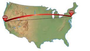
Figure 3-14. A great circle route
The shortest route between two points on the surface of the earth is called a great circle route. To find the great circle route that connects two points, imagine a geometric plane cutting through the earth that passes through the two points and the center of the earth.
On the great circle route from SFO to LGA in Figure 3-14, departing SFO, the desired track is a little less than 90 degrees. Upon arrival at LGA, it appears to be greater than 90 degrees. The desired track heading is constantly changing since it is a circle, not a line. If, however, the difference exceeds several degrees, you need to investigate further to determine the cause.
Check for Route Discontinuities
Some FMS units do not automatically assume that you wish to fly between each of the waypoints that have been entered into the flight plan. When there is a question about how to proceed from one waypoint or instrument procedure to the next, some units insert a “discontinuity” in the programmed route. A route discontinuity indicates that the FMS needs further input from you about how two route segments should be connected. A route discontinuity is shown in Figure 3-15.

Figure 3-15. A route discontinuity and deletion
If you wish to proceed directly from the waypoint that appears before the route discontinuity to the waypoint that appears after, you can simply delete the discontinuity, as shown in Figure 3-15. If the route discontinuity is left in the flight plan, the unit computer will not provide guidance beyond the waypoint that occurs before the discontinuity.
Maintaining Proficiency: Aeronautical Knowledge
It is easy to use an FMS without performing your own calculations for courses, headings, times, distances, and fuel used, but studies have demonstrated that aeronautical skills that are not practiced regularly quickly fade, regardless of experience level or certificates and ratings held. Abnormal and emergency situations (e.g., electrical failure) do occur, so it is important to maintain proficiency in at least making “rule of thumb” calculations on your own.
Coupling the FMS to the Navigation Indicator(s)
Every advanced avionics cockpit features one or more navigation instruments used for course guidance. The navigation indicator (e.g., a horizontal situation indicator (HSI) or electronic HSI) may include one or more course deviation indicators (CDIs), as well as one or more radio magnetic indicators (RMIs). When automatic course/ en route/ approach tracking is desired, you must couple (or connect) the FMS to the autopilot and select “navigation” as the source for the autopilot versus “heading” source, for example. With VOR navigation, that was sufficient. Now, with multiple sources of navigation data available, you must also ensure that the proper navigation information source was selected in the FMS. Every advanced cockpit offers buttons or switches that allow you to choose which navigation indications will be shown on which display or instrument.
This situation becomes complicated in aircraft that contain dual FMS/RNAV installations and redundant selectable displays or instruments. The pilot must learn how to configure each navigation instrument to show indications from each possible navigation source.
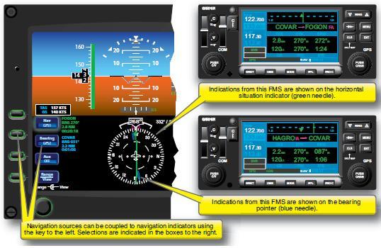
Figure 3-16. Coupling the FMS to navigation instruments
Figure 3-16 shows an example of a primary flight display (PFD) navigation indicator that combines a course deviation indicator (CDI) and a radio magnetic indicator (RMI), and allows the pilot to display indications from one of two FMS on either indicator.
Common Error: Displaying the Wrong Navigation Source
The annunciations showing which navigation sources are displayed on which navigation instruments are often small, so there is significant potential for displaying a navigation source other than the one you intended to select. The consequences of losing track of which navigation signals you are following can be significant: you may think you are steering along one course when in fact you are steering along a different one. Be sure to verify these settings prior to departure, and again each time you make changes to any navigation instrument. Some installations compound this potential with automatic source switching. The most common switching mode is a GPS source to be automatically deselected when the VOR is set to an ILS localizer frequency and a signal is present. Typically, that is not a problem since the pilot intends to switch to the ILS anyway. However, the error arises upon missed approach, when the pilot selects another frequency to follow a VOR missed approach routing. At that point, some units revert back to the previous GPS or other RNAV routing selected instead of the VOR frequency that the pilot just picked. This can result in gross navigation errors and loss of obstruction clearances. In some units, this is a shop programmable or jumper selected option. Check your unit’s features. Always check for correct navigation source selection and cross-check against the published procedure. Be ready and able to fly and navigate manually.
Awareness: Mode Awareness
Mode awareness refers to the pilot’s ability to keep track of how an advanced avionics cockpit system is configured. As shown in Figure 3-16, every advanced avionics system offers an annunciation of which mode is currently set—somewhere in the cockpit! There is no guarantee that you will notice these annunciations in a timely manner. The configuration of these systems must remain part of your mode situational awareness at all times. One strategy is to include “mode checks” as part of your checklist or callout procedures. For example, after programming a route into the FMS, verify that the navigation indicator shows course guidance from the desired source, and that the indication agrees with your estimate of the correct direction and distance of flight.
Essential Skills
1. Determine whether the FMS is approved for the planned flight operation.
2. Determine if your FMS can be used as a primary navigation system for alternate requirements.
3. Understand how entries are made and how the entries can be canceled.
4. Understand how that unit(s) is installed, and how it is programmed or jumpered for optional functions. 5. Determine which navigation sources are installed and functional.
6. Determine the status of the databases.
7. Program the FMS/RNAV with a flight plan, including en route waypoints, user waypoints, and published instrument procedures.
8. Review the programmed flight route to ensure it is free from error.
9. Find the necessary pages for flight information in the databases.
10. Determine which sources drive which displays or instruments, and where the selection controls are located.
11. Determine and understand how to use and program optional functions and equipment installed with FMS/ RNAV basic unit.
En Route Navigation
The FMS provides guidance toward each waypoint in the programmed flight route, and provides information to help you track your progress.
The Active Waypoint
In normal navigation, at any given time, the aircraft is progressing to the next waypoint in the programmed flight route. This next waypoint is called the active waypoint. FMSs typically display the active waypoint on a page dedicated to showing flight progress. While “going to” is the normal function for navigation, nearly all FMSs have the provision to select a point, waypoint, or navaid to navigate “from” that point or position. This can be useful for holding, tracking NDB bearing, grids, etc., and allows the tracking of a bearing with the autopilot engaged and coupled to a navigation source. However, if you are doing an ADF approach, the primary navigation source must be available to support that approach. The page shown in Figure 3-17 indicates that TRACY is the active waypoint. The primary flight display in Figure 2-5 shows the active waypoint (ECA) at the top of the display.
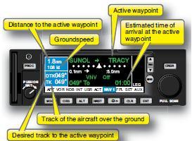
Figure 3-17. Active waypoint, desired track, track, and ETA at active waypoint.
Desired Track
The FMS/PFD/MFD navigation display also shows the desired track to the active waypoint. The desired track is the intended course for the active leg in the programmed flight plan. It is the track that connects the waypoint the aircraft just passed to the active waypoint. On the display in Figure 3-17, the current desired track is the 049-degree course between the SUNOL and TRACY waypoints.
Track
The navigation display shows the aircraft’s track over the ground. The track, which is the result of aircraft heading and winds, tells you which direction the aircraft is actually flying. Winds make it likely that the track and heading will be different. You can get a very good sense of what the winds are doing by comparing the track and heading of the aircraft.
If the aircraft is flying a heading of 090 degrees and the track is 080 degrees, the winds are coming from the south. Notice that having a track indication makes it easy to maintain the desired track. To follow the 049-degree desired track to TRACY upon leaving SUNOL, simply fly the heading that results in a track of 049 degrees. The track display eliminates the traditional method of “bracketing” to find a heading that lets you fly the desired track.
Groundspeed and ETA
The display in Figure 3-17 also shows groundspeed. Again, the navigation display eliminates the need to calculate groundspeed using distance and time. Based on groundspeed and distance from the active waypoint, the navigation page also provides an estimated time of arrival at the active waypoint.
Fuel Used and Time Remaining
Many advanced avionics navigation units offer fuel calculations and fuel state monitoring. Some units automatically load the initial fuel load, while many require the pilot to correctly enter the amount of fuel into the unit as the beginning fuel on board. Some can have installed transducers (sensors) to measure the fuel used, and display fuel used and time remaining at the current consumption rate. Some lower cost units indicate computed fuel consumption values based on fuel burn rates entered by the pilot. This produces an estimate of fuel used and fuel remaining. This estimate is only as accurate as the values entered by the pilot for fuel on board and the consumption rate. Since the pilot is often using the AFM chart data, there is potential for interpretation error. Then, there is the variation error from the factory charts to the specific aircraft being flown. These factors all tend to degrade the accuracy of the fuel calculation based solely on pilot entered data. Other factors such as a fuel burn that is higher than normal, leaks, or other problems are not displayed unless the system actually registers and senses fuel tank realtime status. These errors can affect both types of systems. The pilot must determine what equipment is installed.
Arriving at the Active Waypoint
As the aircraft reaches the active waypoint, there are four new tasks for the pilot:
(1) recognizing imminent arrival at the active waypoint;
(2) leading the turn to avoid overshooting the course to the next waypoint;
(3) making the next waypoint the new active waypoint; and
(4) selecting the desired course to the new active waypoint.
All FMS/RNAV computers offer a sequencing mode that greatly simplifies the performance of the first three of these tasks. Sequencing mode provides three services: waypoint alerting, turn anticipation, and waypoint sequencing.
Waypoint Alerting
The first service performed by the sequencing mode is waypoint alerting. Just prior to reaching each active waypoint, waypoint alerting advises the pilot of imminent arrival at the active waypoint. Waypoint alerting is illustrated in Figure 3-18.
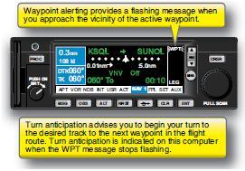
Figure 3-18. Waypoint alerting and turn anticipation
Turn Anticipation
The second service performed by the sequencing mode is turn anticipation. During waypoint alerting and prior to reaching the active waypoint, the FMS indicates that it is time to begin the turn to fly the desired track to the new active waypoint. The timing of turn anticipation is based on the aircraft’s observed groundspeed and the angle of the turn required to track to the next waypoint. If a standard rate turn is begun when the waypoint alerting indication is presented, the pilot should roll out on course when the aircraft reaches the center of the desired track to the new active waypoint. Turn anticipation is also illustrated in Figure 3-18.
When turn anticipation is used, the aircraft does not fly directly over the active waypoint. Rather, the computer commands a turn that “rounds the corner” to some degree, giving priority to having the aircraft roll out on the new desired track to the new active waypoint. This function is illustrated in the upper illustration in Figure 3-19.
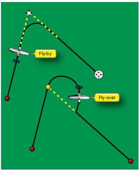
Figure 3-19. Fly-by and fly-over waypoints
Turn anticipation occurs only when the active waypoint is designated as a fly-by waypoint. A fly-by waypoint is one for which the computer uses a less stringent standard for determining when the aircraft has reached it. By contrast, some waypoints are designated as flyover waypoints. The FMS will not use turn anticipation for a fly-over waypoint; instead, the navigation will lead the aircraft directly over the waypoint (hence the name). A missed approach waypoint is a typical example of a fly-over waypoint. A fly-over waypoint is illustrated in Figure 3-19.
Waypoint Sequencing
The third service performed by sequencing mode is waypoint sequencing. Once the aircraft reaches the active waypoint, the FMS automatically makes the next waypoint in the flight plan sequence the new active waypoint. Waypoint sequencing is illustrated in Figure 3-20.
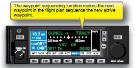
Figure 3-20. Waypoint sequencing
Awareness: Making Waypoint Callouts
To help you stay in touch with the progress of the flight while the FMS automatically performs the navigation task, it is a good practice to announce your arrival (mentally, single pilot; or orally, to the flight crew) at each waypoint in the programmed route. For example, when arriving at SUNOL intersection, you might announce, “Arriving at SUNOL. TRACY is next. The course is 051 degrees, and the ETE is 10 minutes.”
Setting the Course to New Active Waypoint
The last step required when arriving at the active waypoint is to set the course to the next waypoint in the planned route. A PFD such as the one shown in Figure 3-16 automatically sets the new course on the navigation indicator when the RNAV computer is engaged in sequencing mode. When an FMS is combined with a traditional course deviation indicator, the pilot must manually set the new course using the OBS knob, unless it is an EHSI, or is slaved. “Slaved” means that there is a servo mechanism in the instrument that will respond to the navigation unit.
En Route Sensitivity
When operating en route, the FMS maintains a sensitivity of 5 nautical miles (NM); that is, a CDI displaying course indications from the FMS deflects full-scale when the aircraft drifts 5 NM to either side of the desired track to the active waypoint. An aircraft is considered to be en route when it is more than 30 NM from the origin and destination airports programmed into the flight plan. There are and have been some units that use different values. Consult your specific unit’s documentation.
GPS Signal Status
The FMS/RNAV provides position, track, and groundspeed information using signals received from a collection of satellites that are in constant orbit around the Earth when using the GPS navigation source. Although the GPS is highly reliable, satellite reception is sometimes interrupted. Consequently, the pilot must ensure at all times that the system is operational and that it is receiving adequate GPS signals. To simplify this process, all GPS receivers approved for IFR navigation have an automated feature that continually checks the status of the GPS signals. This function is called receiver autonomous integrity monitoring (RAIM). RAIM, which requires adequate simultaneous reception of at least five GPS satellites for IFR navigation reliability, works independently and notifies the pilot when there is a problem with GPS signal reception. When reception problems arise, the FMS/RNAV provides an alert message that notifies the pilot of a GPS reception problem and states that the aircraft position information can no longer be considered reliable. For this reason, regulations require aircraft that are equipped with an RNAV unit using GPS to have an alternate (non-GPS) means of IFR navigation on board (e.g., a VOR receiver) unless the GPS receiver complies with the requirements of WAAS TSO-146B.
For all of the previously mentioned reasons, many manufacturers have coupled inertial navigation units with the FMS to deliver unequalled reliability in navigation. Many more complex FMS units also search or scan for distance measuring equipment (DME) signals and VOR signals as additional navigational sources to compute a “blended” position, which is the best calculation from all of the sources and how the FMS is programmed to “consider” the signals for accuracy. GPS RNAV units usually use only GPS signal sources, but may be able to receive VOR and DME signals as well. In the future, many GPS units will probably receive eLORAN as well, since it is a long range navigation system with greatly improved accuracy as compared to the older LORAN-C. One advantage of the LORAN (“e” or “C”) system is that it is ground based and can be easily maintained, as compared to space-based navigation sources.
Accessing Navigational Information En Route
One of the most useful features of an FMS database is its ability to provide quick access to navigational information. Most units allow the pilot to access information about airports, navigation facilities, airway intersections, and other kinds of waypoints. Figure 3-21 illustrates how one FMS is used to access radio frequencies for an airport.
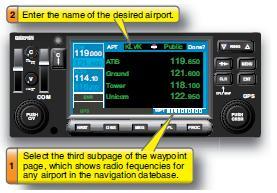
Figure 3-21. Accessing communications frequencies in the FMS
Essential Skills
1. Select and monitor the en route portion of the programmed flight route, determining waypoint arrival, approving turn anticipation, and waypoint sequencing.
2. Approve or select the correct course automatically displayed or manually tuned.
3. Determine if FMS makes fuel calculations and what sensors and data entries are required to be made by the pilot.
4. Ensure that the track flown is that cleared by air traffic control (ATC).
5. Determine that the display CDI sensitivity is satisfactory for the segment being flown.
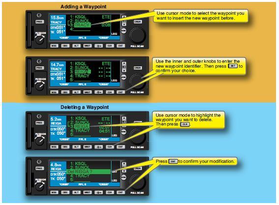
Figure 3-22. Adding and deleting waypoints
En Route Modifications
Part of the challenge of using FMS en route is dealing with modifications to the planned flight route. This section describes five en route modifications.
Adding and Deleting Waypoints From the Programmed Route
All FMS/RNAV units allow en route (not published departure, arrival or approach) waypoints to be added and deleted to the programmed route. These techniques are illustrated in Figure 3-22.
ATC may issue instructions to a point defined by a VOR radial and DME value. The pilot must know how to enter such a waypoint as a user waypoint, name it, and recall it. If the unit’s memory is very limited, the pilot should also be adept at removing the waypoint.
Direct To
Another simple modification is one that requires the pilot to proceed directly to a waypoint. In some cases, the waypoint to fly directly toward is one that already appears in the programmed flight plan. In this case, the pilot simply selects that waypoint in the flight plan and activates the direct-to function, as illustrated in Figure 3-23.
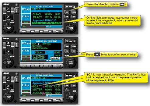
Figure 3-23. Direct-to operation
The direct-to waypoint now becomes the active waypoint. After reaching this waypoint, the system proceeds to the next waypoint in the programmed route. In other cases, you may be asked to fly directly to a waypoint that does not already appear in the programmed flight route. In this case, one strategy is to add the waypoint to the programmed route using the technique illustrated in Figure 3-22, and then proceed directly to the waypoint using the technique illustrated in Figure 3-23. Another option is to use the direct-to function to get the flight started toward the assigned waypoint, and then add the new waypoint to the appropriate place in the programmed flight plan.
Risk: What Lies Ahead on a Direct-To Route?
The direct-to function offers a convenient way to shorten your time and distance en route if ATC authorizes that track. When you perform a direct-to operation, though, remember that the system builds a new track from your present position to the new waypoint. This track does not necessarily correspond to any previously planned airway or route, so it is critical to ensure that your new direct route is clear of all significant obstructions, terrain, weather, and airspace.
Cancel Direct To
ATC may sometimes cancel a previously issued direct-to clearance and ask you to resume the previously cleared route. Most FMSs offer a simple way of canceling a direct-to operation. Figure 3-24 illustrates the procedure for one FMS.
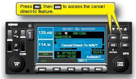
Figure 3-24. Canceling a direct-to operation
Selecting a Different Instrument Procedure or Transition
ATC will sometimes issue an instrument procedure or transition that is different from what you would expect. Entering a new procedure or transition is usually a simple matter of making new menu choices, as illustrated in Figure 3-25. In most units, if you are training or wish to fly the approach again, you must learn how to set the selector or cursor back to the initial fix, which will restart the approach sequence.
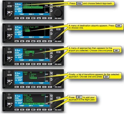
Figure 3-25. Selecting a different instrument procedure or transition
Proceeding Directly to the Nearest Airport
One of the most useful features of an FMS is its ability to provide you with immediate access to a large navigation database. This feature is particularly useful when a suitable nearby airport or navigation facility must be located quickly. Figure 3-26 shows how to locate and proceed directly to the nearest suitable airport using one manufacturer’s system.
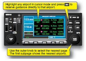
Figure 3-26. Proceeding directly to the nearest airport
Essential Skills
1. Proceed directly to a waypoint in the programmed route.
2. Cancel a programmed or selected waypoint or fix.
3. Select a different instrument procedure or transition.
4. Restart an approach sequence.
5. Immediately find the nearest airport or facility.
6. Edit a flight plan.
7. Enter a user waypoint.
Descent
Making the transition from cruise flight to the beginning of an instrument approach procedure sometimes requires arriving at a given waypoint at an assigned altitude. When this requirement is prescribed by a published arrival procedure or issued by ATC, it is called a crossing restriction. Even when ATC allows a descent at the pilot’s discretion, you need to choose a waypoint and altitude for positioning convenient to start the approach. In either case, descending from a cruising altitude to a given waypoint and altitude requires both planning and precise flying.
Elements of Descent Planning Calculations
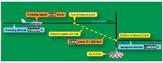
Figure 3-27. The descent planning task
Figure 3-27 illustrates the basic descent planning task. The task begins with an aircraft flying at an assigned cruising altitude. The aircraft must descend to an assigned altitude and reach that assigned altitude at a designated bottom-ofdescent point. The next step is to choose a descent rate and a descent speed. The ultimate goal is to calculate a top-ofdescent point, which is the point at which, if you begin the descent and maintain the planned descent rate and airspeed, you will reach the assigned altitude at the designated bottomof- descent point.
In a basic aircraft, you must rely on manual calculations to perform the descent planning task. In an advanced avionics aircraft, there are two descent planning methods available:
(1) manual calculations, and
(2) the vertical navigation
features of the FMS unit. Skillful pilots use both methods and cross-check them against one another in order to reduce the possibility of error and help keep the pilot “in the loop.”
Manual Descent Calculations
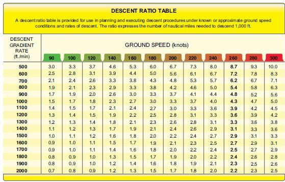
Figure 3-28. Descent ratio table
The simplest technique for calculating the distance required to descend uses a descent ratio. The table in Figure 3-28 lists a descent ratio for many combinations of planned descent speeds and descent rates. Calculating a descent is a simple matter of looking up the descent ratio for your target descent rate and groundspeed, and multiplying the descent ratio by the number of thousands of feet in altitude that you must descend. For example, suppose you are asked to descend from 11,000 feet to meet a crossing restriction at 3,000 feet. Since there is a 200-knot speed restriction while approaching the destination airport, you choose a descent speed of 190 knots and a descent rate of 1,000 feet per minute (fpm). Assuming a 10-knot headwind component, groundspeed in the descent is 180 knots. Referring to the table in Figure 3-28, the planned descent speed and rate indicate a ratio of 3.0. This means that you will need 3 NM for every 1,000 feet of descent. You must descend a total of 8,000 feet (11,000 feet – 3,000 feet). A total of 24 NM is needed to descend 8,000 feet (3 NM × 8 = 24 NM), and must, therefore, begin the descent 24 NM away from the end-of-descent point.
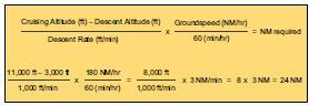
Figure 3-29. Descent formula
Another technique for calculating descents is to use the formula shown in Figure 3-29. A descent table can be found in the front of each set of U.S. Terminal Procedures on page D-1. Working through the formula for the ECA VOR crossing restriction example, 8 minutes is needed to descend 8,000 feet at the planned descent rate of 1,000 fpm. At your planned descent speed of 180 knots, you will cover 3 NM per minute. Thus, in 8 minutes, you will cover 24 NM. Once again, you must start the descent 24 NM prior to ECA to meet the crossing restriction.
Coordinating Calculations with Aeronautical Charts
Regardless of which method is used, it is always a good idea to locate the top-of-descent point chosen on the aeronautical chart. Figure 3-30 shows a chart that covers the area surrounding the ECA VOR. A top-of-descent point 24 NM prior to ECA is located 3 NM before PATYY intersection.
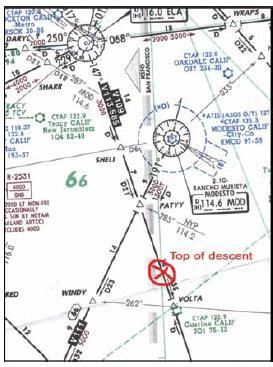
Figure 3-30. Top-of-descent point on an en route chart
Alternate Navigation Planning
Using the aeronautical chart to locate the top-of-descent point has a second advantage. Since regulations require you to have an alternate means of navigation onboard if the computer does not comply with TSO 146B, the aeronautical chart allows you to check minimum altitudes for VOR reception along the route of flight in case VOR navigation is required at any time. The airway that leads to the ECA VOR lists a minimum en route altitude (MEA) of 3,000 feet, which is the clearance altitude.
Calculating Descents with the FMS
Building a descent with an FMS follows the familiar process of entering the basics of the descent into the system, letting the system do the math, and then reviewing what the system has produced. Most FMS units offer a descent planning or vertical navigation (VNAV) page that allows you to enter the details of your descent. Figure 3-31 shows the VNAV page for one manufacturer’s system. Note that there is an entry for each of the descent planning concepts discussed above. Computers perform the calculations using the same formulas and data.
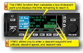
Figure 3-31. Planning a descent with an advanced avionics unit
It is a good idea to cross-check the results of your manual descent calculations with the results produced by the computer. Many RNAV units do not display a waypoint for the planned top-of-descent point. However, there may be an “approaching VNAV profile” message that anticipates the descent point and cues the pilot to begin descending. Caution is advised that some systems calculate the vertical flight path dependent on the current airspeed/groundspeed values. Lowering the nose and gaining airspeed in the descent may confuse you into perceiving a false vertical goal or vertical rate, resulting in failure to meet the crossing restriction with some systems. Determine if the system recomputes the airspeed/groundspeed, or if you must enter the descent airspeed during the VNAV programming.
Managing Speed
Up to this point the focus has been on the task of losing excess altitude. For example, in the situation shown in Figure 3-27, you are faced with the requirement to reduce altitude from 11,000 feet to 3,000 feet. Most descent scenarios also present the challenge of losing excess speed. In piston aircraft of modest performance, losing excess speed seldom requires much forethought. Slowing from a cruising speed of 120 knots to an approach speed of 100 knots requires little planning and can be accomplished quickly at almost any point during a descent. Flying higher performance aircraft requires a closer look at concepts of excess altitude and excess speed. Higher performance piston engines usually require descent scheduling to prevent engine shock cooling. Either the engines must be cooled gradually before descent, or power must be constant and considerable in the descent to prevent excessive cooling. In such instances, a much longer deceleration and gradual engine cooling must be planned to prevent powerplant damage. Additionally, the turbulence penetration or VA speeds should be considered with respect to weather conditions to avoid high speeds in turbulent conditions, which could result in overstressing the airframe. Drag devices such as spoilers can be of great advantage for such maneuvers. In the scenario in Figure 3-27, a cruising speed of 270 knots is inappropriate as the aircraft descends below 10,000 feet, and even more so as it enters Class C airspace. Therefore, descent planning must include provisions for losing excess airspeed to meet these speed restrictions.
Some sophisticated FMSs are able to build in a deceleration segment that can allow the aircraft to slow from the cruise speed to the desired end-of-descent speed during the descent. This type of navigation system allows you to maintain the cruise speed up until the top-of-descent point and calculates the deceleration simultaneously with the descent. A deceleration segment is illustrated in Figure 3-32.
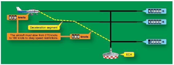
Figure 3-32. A deceleration segment planned by a more sophisticated FMS
Simple FMS units such as GPS RNAV receivers assume that you will slow the aircraft to the planned descent speed before reaching the top-of-descent point. ATC timing may preclude this plan.
Descent Flying Concepts
Probably the most important descent flying concept to understand is that a planned descent is basically a “pathway in the sky,” similar to the glideslope associated with an ILS procedure. If you start down at the planned top-of-descent point, fly a groundspeed of 180 knots, and descend at 1,000 feet per minute (fpm), you will be flying on a fixed path between the top-of-descent point and the bottom-of-descent point. If you maintain the 180-knot and 1,000-foot-perminute descent, you will cross a point 18 NM from ECA at exactly 9,000 feet, a point 12 NM from ECA at 7,000 feet, and a point 6 NM from ECA at exactly 5,000 feet, as shown in Figure 3-33.
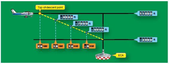
Figure 3-33. Planned descent path as a wire in the sky
If you are at a different altitude at any of these points, you will not cross ECA at the required 3,000 feet unless corrective action is taken. Four things can cause you to drift from a planned descent path:
1. Not following the planned descent rate
2. Not following the planned descent speed
3. Unexpected winds
4. Navigation system not recalculating for airspeed change of descent
Figure 3-34 shows the effect of each situation on the position of the aircraft with respect to the planned descent path.
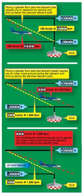
Figure 3-34. Drifting off the planned descent path
Flying the Descent
The key to flying a descent is to know your position relative to the pathway-in-the-sky at all times. If you drift off the path, you need to modify the descent speed and/or descent rate in order to rejoin the descent path. Many FMSs do not give a direct indication of progress during a descent. You must be very familiar with the indirect indications of the VNAV descent. In this case, follow the planned descent rate and speed as closely as possible and be mindful of altitude and position while approaching the crossing restriction fix.
Determining Arrival at the Top-of-Descent
Point All navigation systems provide some type of alert informing the pilot of arrival at the planned top of descent point, and that it is time to begin the descent at the speed and rate entered into the FMS. If air traffic control is able to accommodate your request, the ideal point to begin the descent is at the planned top-ofdescent point. If air traffic control is unable to accommodate such a request, one of two scenarios will ensue: an early descent or a late descent.
Early Descents
Beginning descent before reaching the planned top-ofdescent point means you must set aside descent planning and proceed without the benefit of vertical guidance offered by the navigation system. If, during the descent, the navigation computer does not display position with respect to the planned descent path, you must simply do the best possible to arrive at the crossing restriction at the assigned altitude. If the navigation system does display position with respect to the planned descent path, you can usually recapture the planned descent path and resume flying with vertical guidance from the computer. The basic technique is to initiate descent at a reasonable descent rate that is less than the planned descent rate. If you follow this initial descent rate, you will eventually intercept the planned descent path, as shown in Figure 3-35.
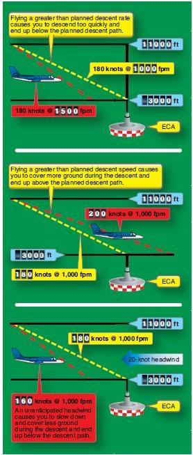
Figure 3-35. Early descent scenario
Late Descents
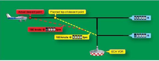
Figure 3-36. Late descent scenario
Beginning the descent beyond the planned top-of-descent point means that you will have the same amount of excess altitude, but a shorter distance and time to lose it, as shown in Figure 3-36.
Since flying beyond the planned A lower speed means you will-of-descent point leaves less time to lose excess altitude, your goal is to minimize the “overrun” distance by slowing the aircraft as soon as a late descent scenario is suspected. A lower speed means you will cover less distance in the same amount of time, and thus be left with more time to lose altitude.
Common Error: Not Considering Winds During Descent
Planning A common error in planning a descent is failing to consider winds and their effect on groundspeed. As illustrated in Figure 3-34, if you fail to take into account a 20-knot tailwind, your groundspeed will be faster than you planned, and you will reach the target waypoint before reaching the assigned altitude.
Essential Skills
1. Determine the descent airspeed to be used with attention to turbulence, aircraft descent profile, and powerplant cooling restrictions.
2. Program, observe, and monitor the top of descent, descent rate, and level-off altitude.
3. Plan and fly a descent to a crossing restriction.
4. Recognize and correct deviations from a planned descent path, and determine which factor changed.
Intercept And Track Course
Intercepting and Tracking a Different Course to the Active Waypoint
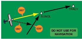
Figure 3-37. A simple course intercept scenario
Figure 3-37 illustrates a common situation. Air traffic control instructs you to fly to a waypoint via an inbound course different from the desired track calculated by the FMS. In the example in Figure 3-37, you are en route to SUNOL intersection. The FMS has calculated a desired track of 060 degrees, but ATC has instructed you to fly a heading of 080 degrees to intercept a 009-degree course to SUNOL.
The FMS is set to take the aircraft to SUNOL intersection, but via an inbound course different from the one ATC has cleared you to follow. Therefore, you need to be a means of programming the FMS to follow your choice of course instead of the desired track that it has identified.
The Nonsequencing Mode
Every IFR-capable FMS/RNAV unit offers an alternative mode of operation, the nonsequencing mode, which allows you to perform this particular task. Like the OBS knob which allows you to select VOR radials, the nonsequencing mode allows you to select courses to or from an active waypoint. The nonsequencing mode differs from the sequencing mode in two important ways:
1. Nonsequencing mode allows you to select a different inbound course to the active waypoint. For this reason, some manufacturers refer to the nonsequencing mode as OBS (hold or suspend) mode, which suggests similarity to the OBS knob found on traditional VOR indicators. As the OBS knob allows you to select inbound VOR radials, the nonsequencing mode allows you to select inbound courses to an active waypoint.
2. Nonsequencing mode stops the waypoint sequencing feature of the FMS/RNAV unit. If engaged in nonsequencing mode, the FMS/RNAV program does not automatically sequence to the next waypoint in the flight plan when the aircraft arrives at the active waypoint. Every FMS/RNAV offers a way to switch to the nonsequencing mode. There is typically a button marked OBS (or Hold), and an OBS or course selection knob to select an inbound course to the active waypoint. Figure 3-38 illustrates the procedure for one particular FMS.
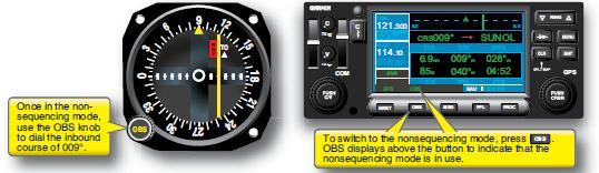
Figure 3-38. Setting a different course to the active waypoint
Once you switch to nonsequencing mode and select the inbound course of 009°, the navigation indicator reflects aircraft position with respect to the 009° course. The navigation indicator in Figure 3-38 shows that you are west of course. The assigned heading of 080° provides an acceptable intercept angle. As you fly the 080° heading, the needle centers as you reach the 009° course. Once the 009° course is reached and the needle has centered, you can turn to track the 009° course inbound to SUNOL.
It is important to remember that the nonsequencing mode suspends the FMS/RNAV’s waypoint sequencing function. If you reach SUNOL and the unit is still set in the nonsequencing mode, it will not sequence on to the next waypoint. Generally, once established on a direct course to waypoint or navaid, switching back to sequencing (releasing the Hold or Suspend function) mode allows the FMS/RNAV to continue to the programmed point and thence onward according to the programmed routing. Setting the computer back to the sequencing mode is usually accomplished by pressing the OBS (Hold or Suspend) button again.
Common Error: Forgetting To Re-Engage Sequencing Mode After Course Intercept
By far the most common error made with the nonsequencing mode is forgetting to re-engage the sequencing mode once the course has been intercepted. The result is that the FMS will not sequence to the next waypoint in the flight route upon reaching the active waypoint. The best indicator of this event is the “To/From” navigation display showing “From.” Normally all FMS fly “To” the waypoint, unless that unit does holding patterns. Flying “From” a waypoint can only be done in the “OBS”/“Hold”/“Suspend” mode.
Awareness: Remembering To Make Needed Mode Changes
The use of the sequencing and nonsequencing modes illustrates another aspect of maintaining good mode awareness—remembering to make required mode changes at future times during the flight. Remembering to do tasks planned for the future is a particularly error-prone process for human beings. Aviation’s first line of defense against such errors is the checklist. Creating your own checklist or callout procedures for maneuvers such as course intercepts is a good way to minimize this error. For example, a simple callout procedure for the course intercept maneuver might commence when the aircraft nears the point of interception. “Course is alive. Course is captured. Changing back to sequencing mode.”
Intercepting and Tracking a Course to a Different Waypoint
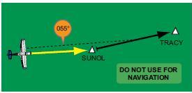
Figure 3-39. A more complicated course intercept scenario
Figure 3-39 illustrates a slightly more complicated request often made by air traffic control. While en route to SUNOL, ATC instructs you to fly a heading of 060° to intercept and track the 049 course to TRACY. This situation requires two separate tasks: changing not only the inbound course, but also the active waypoint. The first step is to change the active waypoint using the direct-to function, as illustrated in Figure 3-40. Remember, though, that if you use the direct-to function to make TRACY the active waypoint, the FMS calculates a desired track that takes you from the present position to TRACY intersection.
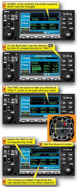
Figure 3-40. Intercepting a course to a different waypoint
The second step, illustrated in Figure 3-40, is to change the desired track to TRACY by setting the computer in the nonsequencing mode and selecting the inbound course. You now continue on the assigned heading until the needle centers, then set the FMS back to the sequencing mode, and continue inbound on the assigned course to TRACY intersection.
Common Error: Setting the Wrong Inbound Course During a Course Intercept
One common error made during course intercepts is to select the wrong course to the active waypoint. Some FMSs automatically set the course indicator (“slew” the needle) to the inbound course. Where this capability does not exist, pilots occasionally select the heading that they have been assigned to fly to intercept the course instead of the inbound course. The outcome of this error is illustrated in Figure 3-41.
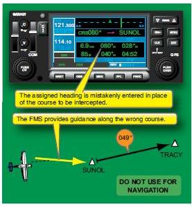
Figure 3-41. Selecting the wrong course to the active waypoint
Common Error: Setting the Wrong Active Waypoint During a Course Intercept
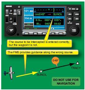
Figure 3-42. Setting the wrong active waypoint
Another common error is failing to realize that ATC has instructed you to intercept a course to a different waypoint. Figure 3-42 shows the outcome when the pilot neglects to set TRACY as the active waypoint in the previous example. The FMS offers guidance along the correct course, but to the wrong waypoint.
Catching Errors: A Helpful Callout Procedure for Course Intercepts
The following is a useful technique for avoiding two errors commonly made during course intercept maneuvers. Ask yourself the following two questions when working your way through any course intercept maneuver:
Question #1: Where am I going?
Point to the active waypoint on the navigation page and make sure it shows the waypoint that you wish to fly toward.
Question #2: How am I getting there?
Point out the desired track to the active waypoint on the navigation page. If it is not the one you want, engage the nonsequencing mode and select the course you want.
Essential Skills
1. Program and select a different course to the active waypoint.
2. Select the nonsequencing waypoint function (OBS, Hold, or Suspend) to select a specified navigation point.
3. Reactivate the sequencing function for route navigation.
Holding
The FMS/GPS unit’s nonsequencing mode provides an easy way to accomplish holding procedures. When instructed to hold at a waypoint that appears in the route programmed in the FMS/GPS unit, simply engage the nonsequencing mode prior to reaching the waypoint. With waypoint sequencing suspended, you can determine and fly the appropriate holding pattern entry, select the inbound holding course using the course selector (OBS in some) knob or buttons, and fly the holding pattern while timing the outbound leg. Some FMSs can automatically enter the holding pattern, and continue to hold if programmed. As the aircraft repeatedly crosses the holding waypoint with each turn in the hold, the holding waypoint remains the active waypoint. When you are cleared out of the holding pattern for the approach or to another point, you should select the sequencing mode or cancel the suspension before reaching the holding waypoint for the last time. When you pass the holding waypoint in sequencing mode, the FMS/GPS unit will then sequence to the next waypoint in the route. This procedure is demonstrated in Figure 3-43.
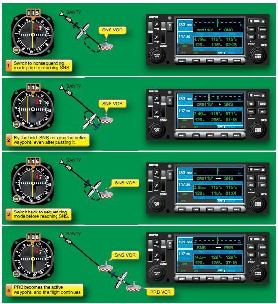
Figure 3-43. Using the nonsequencing mode to fly a hold
Preprogrammed Holding Patterns
Some FMS/GPS units insert preprogrammed holding patterns into published instrument procedures. The purpose of a preprogrammed holding pattern is to relieve you of many of the tasks described above for flying a holding pattern.
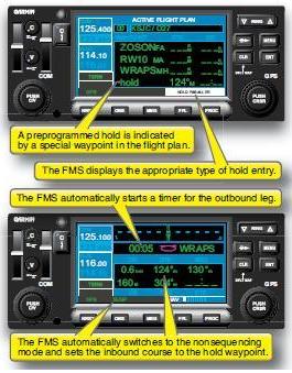
Figure 3-44. A preprogrammed holding procedure
Figure 3-44 illustrates a preprogrammed holding pattern that appears at the end of a missed approach procedure.
As the FMS/GPS unit shown in Figure 3-44 sequences to a preprogrammed holding pattern, the navigation displays a message indicating the type of holding entry required based on the aircraft’s current track. The system then automatically switches to a special nonsequencing mode that not only stops waypoint sequencing, but also sets the inbound course to the holding waypoint. This special nonsequencing mode is different from the nonsequencing mode you engage manually. In Figure 3-44, this system uses the term suspend mode (SUSP) to signify the nonsequencing mode that is automatically engaged during a preprogrammed holding procedure. Depending on the type of holding procedure, the unit may or may not automatically switch back to the sequencing mode after the aircraft crosses the holding fix. As always, you must be careful to maintain constant mode awareness.
Common Error: Mismanaging the Sequencing/ Nonsequencing Modes
During a Hold Mismanagement of the sequencing and nonsequencing modes during a holding procedure is another common error. Failing to switch the FMS/GPS RNAV to the nonsequencing mode prior to reaching the holding waypoint, or prematurely switching the unit back to the sequencing mode once established in the hold, can prompt the FMS/GPS to sequence past the holding waypoint. In this case, you are left without guidance along the inbound holding course.
Essential Skills
1. Select a preprogrammed holding pattern, or nonsequencing mode.
2. Select and setup a non-preprogrammed holding pattern inbound course.
3. Determine the proper sequence of software commands for the holding pattern, transition to approach, approach, and MAP navigation.
ARCS
FMS and some GPS units simplify the problem of tracking arcs, which are curved courses between waypoints. The key feature of an arc is that there is no one bearing that takes you from one waypoint to the next. Rather, depending on its length, an arc requires you to follow a gradually changing heading toward the active waypoint. The example in Figure 3-45 illustrates how an FMS is used to fly a DME arc procedure.
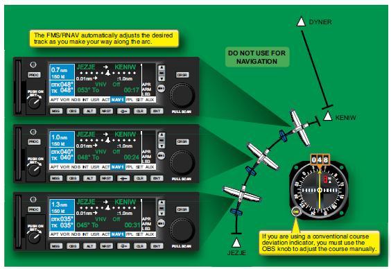
Figure 3-45. Flying an approach with an arc
Essential Skills
1. Select an approach procedure with an arc.
2. Select the course, or determine that automatic course CDI setting will occur.
GPS and RNAV (GPS) Approaches
An IFR-capable GPS RNAV/FMS with qualified GPS receiver(s) can be used as the sole means of navigation for several kinds of instrument approach procedures, but you need to know which approaches can be used with your particular GPS RNAV unit. The following paragraphs review the approaches available today.
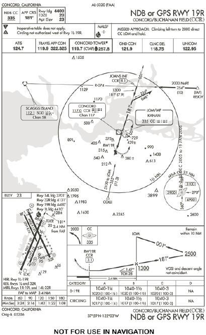
Figure 3-46. A GPS overlay approach
A GPS overlay approach is illustrated in Figure 3-46. The basic benefit of the GPS overlay approach is that it allows use of an IFR approved GPS receiver to navigate and fly a conventional nonprecision approach. From the previous text, you must know how to hold the specific sequences and how the unit can be stopped from sequencing through the flight plan. Many approaches require holding or a procedure turn to orient the aircraft correctly for the approach course. If you cannot control the sequencing of the FMS, you will lose course guidance upon the turn for outbound holding, as the FMS/GPS receiver sequences for the course beyond the holding fix.
GPS overlay approaches are named for the conventional system upon which the approach is based, but include the word GPS. The approach in Figure 3-46 is based on an existing NDB approach. If the aircraft has an IFR-approved FMS/GPS RNAV, you may use that guidance to fly the GPS overlay approach. It is not necessary for the aircraft to have the conventional navigational equipment on board for that approach, but conventional navigational avionics will be required for any required alternate, if equipped with a TSO- 129 GPS receiver. If conventional avionics are installed in the aircraft, there is no requirement to use the equipment in any way, although monitoring is always a good practice. If the installed FMS/GPS receiver is TSO-145A/146A WAAS certified, no other navigation equipment is required.
One common pitfall of all advanced avionics approaches is the sometimes limited notification of the position along the approach path. In many instances, you must read the name of the waypoint to confirm where the aircraft is headed. It is easy for you to be preoccupied with cross-check and flying duties to miss a waypoint change and be of the mindset that you have one more waypoint to go before descent, or even worse, before a missed approach. Two main values always to include in the cross-check are:
1. Verification of the waypoint flying “to.”
2. Verification that the distance to the waypoint is decreasing. Upon reaching the missed approach point (MAP), the system will automatically go to “Suspend,” “Hold,” or “OBS” at the MAP, and the distance to go will begin counting up or increasing as the distance from the MAP behind increases. Acknowledge the MAP and the beginning of the MAP segment by an action (button, knob, etc.) to allow sequencing to the holding point or procedure.
Not all units delay commanding a turn prior to reaching the specified turn altitude. You must know the required navigation courses and altitudes. The FMS/GPS unit may not be 100 percent correct, especially if an ADC is not installed.
Since the FMS/GPS automatically switches to the approach sensitivity, you must not attempt to use the “approach” mode of the autopilot at that time, unless the autopilot documentation specifically directs the use of that mode at that time. Using that mode would make the autopilot hypersensitive and too responsive to navigation signals. GPS stand-alone approaches are nonprecision approaches based solely on the use of the GPS and an IFR-capable FMS with GPS navigation receiver or GPS RNAV.
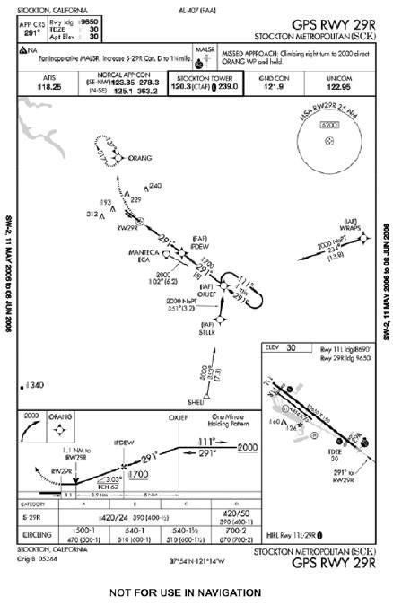
Figure 3-47. GPS stand-alone approach
A GPS standalone approach is shown in Figure 3-47. RNAV (GPS) approaches are designed to accommodate aircraft equipped with a wide variety of GPS receivers. An RNAV (GPS) approach procedure is shown in Figure 3-48. A GPS approach typically offers different approach minimums (and sometimes different missed approach points) depending on the type of GPS receiver, aircraft, and installation being used to complete the approach.
 approach.JPG)
Figure 3-48. RNAV (GPS) approach
LNAV
LNAV (lateral navigation), like a conventional localizer, provides lateral approach course guidance. LNAV minimums permit descent to a prescribed minimum descent altitude (MDA). The LNAV procedure shown on the chart in Figure 3-48 offers an MDA of 1,620 feet.
LNAV/VNAV
LNAV/VNAV (lateral navigation/vertical navigation) equipment is similar to ILS in that it provides both lateral and vertical approach course guidance. Since precise vertical position information is beyond the current capabilities of the global positioning system, approaches with LNAV/ VNAV minimums make use of certified barometric VNAV (baro-VNAV) systems for vertical guidance and/or the wide area augmentation system (WAAS) to improve GPS accuracy for this purpose. (Note: WAAS makes use of a collection of ground stations that are used to detect and correct inaccuracies in the position information derived from the global positioning system. Using WAAS, the accuracy of vertical position information is increased to within 3 meters.) To make use of WAAS, however, the aircraft must be equipped with an IFR approved GPS receiver with WAAS signal reception that integrates WAAS error correction signals into its position determining processing. The WAAS enabled GPS receiver shown in Figure 3-49 allows the pilot to load an RNAV approach and receive guidance along the lateral and vertical profile shown on the approach chart in Figure 3-48.
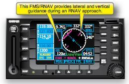
Figure 3-49. WAAS data provides lateral and vertical guidance
It is very important to know what kind of equipment is installed in an aircraft, and what it is approved to do. It is also important to understand that the VNAV function of non-WAAS-capable or non-WAAS-equipped IFR approved GPS receivers does not make the aircraft capable of flying approaches to LNAV/VNAV minimums.
LPV
LPV can be thought of as “localizer performance with vertical guidance.” Procedures with LPV minimums use GPS information to generate lateral guidance, and IFR-approved GPS/WAAS receivers to generate vertical guidance similar to an ILS glideslope. Several manufacturers now offer FMS/ GPS RNAV units capable of flying approaches to LPV minimums.
GPS or RNAV (GPS) Approach Waypoints
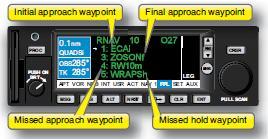
Figure 3-50. Approach waypoints.
Figure 3-50 shows a GPS approach loaded into an FMS/GPS RNAV. As previously noted, approaches must be selected from a specific approach menu in the FMS. The software then loads all of the waypoints associated with that procedure from the database into the flight route. It is not possible for you to enter or delete, separately or individually, waypoints associated with the approach procedure.
Once loaded, a GPS or RNAV (GPS) approach is shown in the FMS display as a collection of waypoints with a title that identifies the approach. Four waypoints in every approach procedure have special designations:
(1) initial approach waypoint;
(2) final approach waypoint;
(3) missed approach waypoint; and
(4) missed holding waypoint.
Flying a GPS or RNAV (GPS) Approach
Most FMS require the pilot to choose whether to simply load, or load and activate, instrument approach procedures. When ATC tells you to expect a certain approach, select that approach from the menu and load it into the flight plan. Loading an approach adds its component waypoints to the end of the flight plan, but does not make them active. Once ATC clears you for the approach (or, alternatively, begins providing radar vectors to intercept the final approach course), you must remember to activate the approach to receive course guidance and auto-sequencing. You must be careful not to activate the approach until cleared to fly it, however, since activating the approach will cause the FMS to immediately give course guidance to the initial approach fix or closest fix outside the final fix, depending on the unit’s programming. In the case of a vectors-to-final approach, activating the vector-to-final causes the FMS to draw a course line along the final approach course.
Once you have loaded and activated the GPS or RNAV (GPS) approach procedure, flying it is similar to flying between any other waypoints in a programmed flight route. However, you must be prepared for two important changes during the approach.
Terminal Mode
The first important change occurs when the aircraft reaches a point within 30 NM of the destination airport. At this point, regulations require that every GPS-based FMS/ RNAV unit increase its sensitivity and integrity monitoring (receiver autonomous integrity monitoring, or RAIM, which continuously checks GPS signal reliability and alerts you if RAIM requirements are not met). If the system determines that RAIM requirements are met, the FMS/GPS RNAV unit automatically switches from en route sensitivity to terminal sensitivity within 30 NM of the destination airport. Terminal mode increases the sensitivity of the course deviation indicator (CDI) from 5 NM to 1 NM. The FMS/GPS RNAV displays an annunciation to let you know that it has switched from en route sensitivity to terminal mode.
Approach Mode
The second important change occurs 2 NM prior to reaching the final approach waypoint. At this point, the FMS/GPS RNAV unit automatically switches to approach sensitivity. At this stage, the FMS/GPS RNAV further increases RAIM requirements, and increases the CDI sensitivity from 1 NM to 0.3 NM (i.e., a full-scale CDI deflection occurs if you are 0.3 NM or more from the desired course).
As long as the annunciation for approach mode is displayed, you may continue the approach. If, however, the computer fails to switch to approach mode, or the approach mode annunciation disappears, you must fly the published missed approach procedure. You are not authorized to descend further or to the MDA. Making changes to the FMS/ GPS RNAV after reaching the 2 NM point could result in automatic cancellation of the approach mode.
Approach Not Active
If you arrive at the final approach waypoint and the approach mode is not active, you must fly the missed approach procedure. There should be no attempt to activate or reactivate the approach after reaching the final approach fix using any means—simply fly the missed approach procedure.
Vectored Approaches
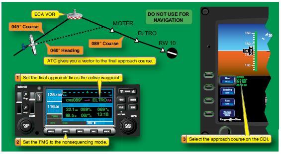
Figure 3-51. A vectored RNAV approach
As in conventional approaches, it is common for air traffic control to issue vectors to a GPS or RNAV (GPS) final approach course. Flying a vectored GPS or RNAV (GPS) approach is a simple matter of using the course intercept technique described in the previous section. The technique is illustrated again in Figure 3-51.
Many FMS/GPS RNAV units offer an automated solution to the problem of flying an approach in which the pilot receives vectors to the final approach course. Once ATC begins providing vectors to intercept the final approach course, you should activate the computer’s “vectors-to-final” feature, which draws a course line along the final approach course. This feature helps you maintain situational awareness while being vectored because the assigned heading is clearly seen in relation to the final approach course. As already noted, you should monitor carefully to ensure that the FMS/GPS RNAV unit switches to approach mode within 2 NM of the final approach fix (FAF).
Figure 3-51 shows the vectors-to-final feature. The procedure required to use the vectors-to-final feature is illustrated in Figure 3-52.
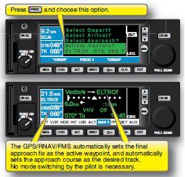
Figure 3-52. The vectors-to-final feature
When set to use the vectors-to-final feature, many FMS/ GPS RNAV units automatically set the FAF as the active waypoint; and set the final approach course as the desired track to the active waypoint.
Awareness: Briefing the Approach
As with any instrument approach, you should develop and consistently use a briefing technique to ensure that you think through all the steps necessary to set up the approach correctly. One technique uses the mnemonic ICE-ATM:
I Identify primary navigation frequency
C Course (inbound) set
E Entry (direct, teardrop, parallel)
A Altitudes for transition, initial, final, and missed approach segments
T Timing/Distance(s)
M Missed approach procedure
Another briefing technique uses the mnemonic FARS:
F Frequencies set and identified
A Altitudes for transition, initial, final, and missed approach segments
R Radial (inbound course) noted and set
S Special notes (including missed approach procedure)
Common Error: Forgetting To Verify the Approach Mode
The most common error made during a GPS/RNAV approach is to forget to ensure that the approach mode has indeed engaged prior to beginning a descent to minimums. Routinely checking for the approach indication 2 NM before the final approach waypoint not only prevents this type of error, but also gives you a minute or so to remedy some situations in which the approach mode has not engaged.
Common Error: Using the Wrong Approach Minimums
Listing several different approach minimums on a single instrument approach chart introduces the possibility of another simple type of error: using the wrong approach minimums. One way to avoid mix-ups is to verbalize the equipment being used and type of procedure being flown, and then search for the approach minimums with these details in mind. You must be absolutely certain of the certification, approval, and installed options of the advanced avionics equipment prior to flight planning.
Common Error: Forgetting To Reengage Sequencing Mode Prior to Final Approach Waypoint
A common mistake made by pilots when they are learning to fly vectored approaches without a vectors-to-final feature is forgetting to set the FMS/GPS RNAV back to sequencing mode once established on the approach course. This error prevents the FMS/ GPS RNAV unit from switching to the approach mode 2 NM prior to the FAF. If you pass the final approach fix and the computer is still in nonsequencing mode, the approach mode will be disabled and you must fly the missed approach, report the missed approach and request another approach.
Essential Skills
1. Load and activate a vectored GPS or RNAV (GPS) approach.
2. Select a vectored initial approach segment.
3. Determine the correct approach minimums and identify all pertinent mode transitions.
4. Determine the published missed approach point (MAP), courses, altitudes, and waypoints to fly.
5. Determine how missed approach guidance is selected.
Course Reversals
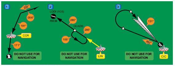
Figure 3-53. Three types of course reversals
Figure 3-53 shows three common course reversals:
(1) 45-degree procedure turn,
(2) holding pattern, and
(3) teardrop procedure.
Course reversals are handled in the same way as holding procedures, by using the FMS/GPS’s nonsequencing mode. As you arrive at the initial approach waypoint, the unit’s nonsequencing mode should be engaged to prevent it from immediately sequencing to the next waypoint in the approach. After completing the course reversal, be sure to re-engage the system’s sequencing mode to continue the approach.
The navigation unit in Figure 3-54 requires that you manually switch between the sequencing and nonsequencing modes.
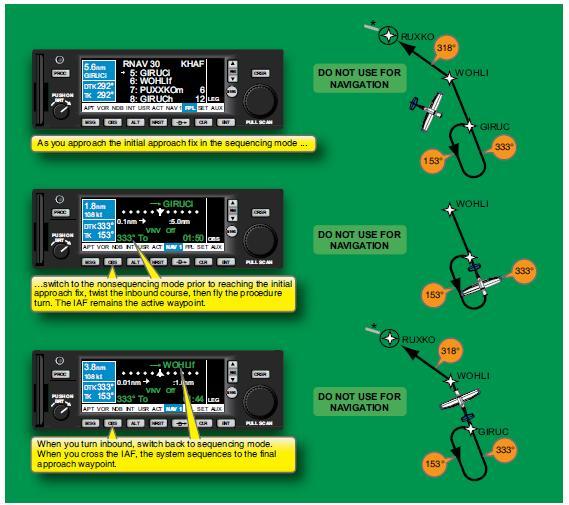
Figure 3-54. Using the nonsequencing mode to accomplish a course reversal
Preprogrammed Course Reversals
Some FMS/GPS units insert preprogrammed course reversals into published instrument approach procedures. The purpose of a preprogrammed course reversal is to relieve you from the mode switching and course selection tasks associated with course reversals.
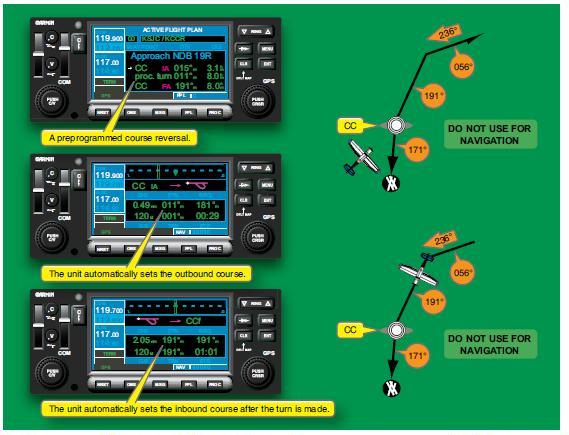
Figure 3-55. Using the nonsequencing mode to accomplish a course reversal
The FMS/GPS unit in Figure 3-55 includes a preprogrammed course reversal. This unit automatically sets the outbound course for the outbound portion of the course reversal. Once the turn inbound has been made, the unit automatically sets the inbound course back to the final approach waypoint.
This FMS/GPS unit does not switch between sequencing and nonsequencing modes for a 45-degree course reversal (although it does for a holding-type course reversal). Whether it is done manually, automatically, or not at all, you must be sure that the system is engaged in sequencing mode before reaching the final approach waypoint after the course reversal is completed. The FMS/GPS will switch to the approach mode only if the system is engaged in the sequencing mode.
Common Error: Mismanaging the Sequencing/ Nonsequencing Modes During a Course Reversal
Neglecting to switch the FMS/GPS from the nonsequencing mode prior to reaching the initial approach waypoint and neglecting to switch the system back to the sequencing mode prior to passing the final approach waypoint are common errors made during course reversals.
Essential Skills
1. Select a type of course reversal procedure.
2. Determine the correct sequence of mode control actions to be accomplished by the pilot.
Missed Approaches
The FMS/GPS unit’s nonsequencing mode provides an easy way to fly missed approach procedures, such as the one illustrated in Figure 3-56.
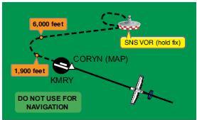
Figure 3-56. A missed approach procedure
The missed approach procedure shown in Figure 3-56 requires you to climb to 1,900 feet, turn right and climb to 6,000 feet, then proceed direct to the SNS VOR.
The FMS/GPS helps you navigate between waypoints, which are geographically fixed locations. But where will the aircraft reach 1,900 feet on the missed approach procedure at Monterey? This depends on what aircraft you are flying and the chosen rate of climb. A single-engine airplane might be four miles away by the time it reaches 1,900 feet. A small jet might reach 1,900 feet by the end of the runway. The problem is that, given the way the FMS/GPS system uses waypoints, there is no one way to represent the climbs and turns required on a missed approach procedure.
To address this issue, all FMS/GPS RNAV units automatically suspend waypoint sequencing when you reach the missed approach point. The unit waits until you acknowledge the passing of the MAP before it continues the sequencing. When the aircraft has gained the published altitudes and complied with the initial MAP procedures, you can safely proceed to the missed approach holding waypoint, being mindful of any altitude requirements. A waypoint for the missed approach holding point is included as part of the missed approach procedure. In the example above, you can make the missed approach holding waypoint the active waypoint, and re-engage the sequencing mode upon reaching 6,000 feet. You now have sequencing mode guidance to the missed approach holding waypoint. The procedure for one FMS/GPS is illustrated in Figure 3-57.
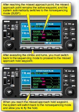
Figure 3-57. Flying a missed approach procedure
Since the hold at SNS is part of the published missed approach procedure, it can be carried out using the same technique used to perform a holding pattern. Some FMS/GPS units will automatically switch to the nonsequencing mode when you reach the hold fix. Other units may advise you to switch manually to the nonsequencing mode.
Recognizing the Missed Approach Point
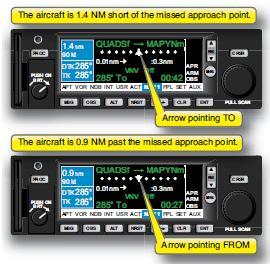
Figure 3-58. Recognizing the missed approach waypoint
With any type of navigation equipment, it is important to be able to determine when you have reached the missed approach point. The missed approach point indications given by FMS/GPS units are sometimes subtle. Consider the two navigation displays shown in Figure 3-58. The display in the top graphic of Figure 3-58 shows the aircraft approaching the missed approach point, 1.4 NM away.
Now consider the display in the bottom graphic of Figure 3-58. The distance from the missed approach point might suggest that the aircraft is now even closer to the missed approach point. However, the TO/FROM flag on the course deviation indicator shows that the aircraft has in fact passed the missed approach point. It is tempting to monitor the distance from the missed approach point as it decreases to 0.0 NM. The problem is that, depending on how accurately the pilot flies, the distance may never reach 0.0 NM. Rather, it may simply begin to increase once you have passed abeam the missed approach point. It is, thus, important to check not only the distance from the missed approach point, but also the TO/FROM flag or arrow. In the rush of a missed approach, this small clue (arrow direction change) can be difficult to read and very easy to misinterpret.
Complying With ATC-Issued Missed Approach Instructions
ATC sometimes issues missed approach instructions that are different from those published on the approach chart. In this case, use the techniques described earlier to insert new waypoints into the route, and/or to intercept and track courses to those waypoints.
Setting Up Next Procedure in Hold
Once in the missed approach holding pattern, the next task is deciding where to go next and programming the new flight plan into the FMS/GPS unit. In this high workload situation, 3-42 it is especially important to be very proficient with the menus, functions, and “switchology” of a particular unit. If the aircraft is equipped with an autopilot, it is also essential to have a thorough understanding of how the autopilot interacts and interfaces with the FMS/GPS navigation equipment.
Common Error: Noncompliance With Initial Missed Approach Instructions
The immense capability of the FMS/GPS may tempt you to follow its directions rather than fly a missed approach procedure exactly as published on the instrument approach procedure chart. Always fly procedures as published, especially with respect to the initial climb and turn instructions. GPS as a line-of-sight navigation aid can display courses and distances to a ground-based navaid even though the navaid is on the other side of a mountain range and itself cannot be received, because GPS signals are spaced based.
Essential Skills
1. Acknowledge a missed approach procedure.
2. Set the FMS/GPS for a return to the same approach to fly it again.
3. Select a different approach while holding at a missed approach holding waypoint.
4. Program an ATC specified hold (user waypoint) point for selection after the published MAP/hold procedure.
Ground-Based Radio Navigation
Configuring FMS To Receive Ground-Based Radio Navigation Signals
Most advanced avionics systems include receivers for conventional radio navigation signals from VOR, localizer, and glideslope transmitters. To display these signals on the navigation display indicator(s), you need two fundamental skills.
Tuning and Identifying Radio Navigation Facilities
The first fundamental skill in ground-based radio navigation is tuning and identifying a ground-based radio navigation facility. Figure 3-59 illustrates how a VOR station can be tuned using two different systems.
Some systems automatically attempt to identify ground-based radio navigation facilities that are selected by the pilot. Note the identifier that appears beside the selected frequency in the upper left corner of the PFD in Figure 3-59 (116.00 = ECA).
Displaying Radio Navigation Signals on the Navigation Indicator
The second fundamental skill is displaying indications from a ground-based radio navigation facility on the navigation display indicator in the aircraft. In addition to setting the navigation indicator to display indications from different navigation sources, you must also know where to look to double-check which indications are currently being displayed. It is crucial to remain constantly aware of the navigation source for each indicator. Many systems use color coding to make a visual distinction between different RNAV navigation sources (GPS, INS, etc.) and ground-based radio navigation sources.
Awareness: Using All Available Navigation Resources
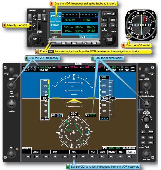
Figure 3-59. Tuning navigation radio frequencies
Looking at the two systems shown in Figure 3-59, you can see that two VOR frequencies appear in the active windows at all times, regardless of whether VOR or GPS is being used as the primary navigation source. To maximize situational awareness and make best use of this resource, it is a good practice to keep them tuned to VOR stations along your route of flight. If you have two navigation indicators, you can have one indicator set to show GPS course indications, with the other to show VOR indications. Used in this way, VOR and GPS can serve as backups for each another.
Flying a Precision Approach Using Ground-based Navigation Facilities
Flying a precision approach requires tuning the required frequencies, configuring the navigation indicator to display localizer course indications, and flying the approach. For aircraft equipped with multiple navigation radios, the localizer frequency can go into one receiver, while a second navigational facility used as a cross-radial can be set in the other receiver. As you come within range of the localizer and glideslope, the course deviation and glideslope indicators will show position with respect to the localizer and glideslope.
Flying a Nonprecision Approach Using Ground- Based Navigation Facilities
Nonprecision approaches such as VOR, localizer, and LDA approaches are flown using the same procedures used to fly a precision approach. If the aircraft is equipped with an autopilot, be sure to develop a thorough understanding of how the autopilot works with the FMS. While these systems automate some tasks, others (e.g., flying the procedure turn course reversal) maybe left to the pilot.
Maintaining Proficiency: Practicing All Navigation Skills
Advanced avionics systems offer you several ways to navigate. Numerous studies have demonstrated the potential for deterioration of navigational skills that are not regularly practiced. It is important to get regular practice using groundbased navigation facilities as well as RNAV sources. One way to maintain proficiency is to consistently use ground-based navigational facilities as a backup to RNAV systems.
Essential Skills
1. Select any type of ground-based radio navigation approach.
2. Correctly tune and set up the conventional navigation receiver for that procedure.
3. Correctly monitor the navaid for properly identification and validity.
4. Correctly select and be able to use the desired navigation source for the autopilot.
Chapter Summary
Navigation has been freed from the constraints of channeling all flight traffic along one path. The area navigation capabilities found in advanced avionics receiving signals from other than conventional line-of-sight ground-based aviation navaids and the compact size and reliability of microchips now allow efficient, accurate air travel. Integrated databases facilitated by large reliable memory modules help you to select routes, approaches, and avoid special use airspace.
With this freedom of movement, you must expend more time learning the system and how to do the preflight entries or programming. In addition to current charts, you must now verify the currency of the advanced avionics databases. The aircraft owner must also allocate the funding to maintain the currency of the databases.
You now have access to a tremendous amount of data. The methods of data selection and display must be learned and then decisions made about which display formats to use at which times. VOR/DMEs are simple receivers to tune and use. To use current flight management systems and area navigation units, you may need to study books that are larger than the actual units themselves. You must know the quality of maintenance for advanced avionics units and the qualifications of the systems to determine appropriate uses of the equipment.
Since advanced avionics have different displays, navigation sources, functions, and features, the pilot must always be aware of the mode selected, the data source(s), and the function selected. Pilot lack of attention to navigation can have dire consequences, including notification of the next of kin.
Copyright © 2008 AirplaneGroundSchools.com | All Rights Reserved
Design G. Wolfgang | W3C XHTML 1.0 | W3C CSS 2.0
Courtesy Open Web Design![]() Thanks to Florida Vacation Homes
Thanks to Florida Vacation Homes