Airplane Ground Schools
Knowledge of Flying is Our passion.
Serving the General Aviation Community
|
|
The en route phase of flight has seen some of the most dramatic improvements in the way pilots navigate from departure to destination. Developments in technology have played a significant role in most of these improvements. Computerized avionics and advanced navigation systems are commonplace in both general and commercial aviation.
The procedures employed in the en route phase of flight are governed by a set of specific flight standards established by Title 14 of the Code of Federal Regulations (14 CFR), Federal Aviation Administration (FAA) Order 8260.3, United States Standard for Terminal Instrument Procedures (TERPS), and related publications. These standards establish courses to be flown, obstacle clearance criteria, minimum altitudes, navigation performance, and communications requirements. For the purposes of this discussion, the en route phase of flight is defined as that segment of flight from the termination point of a departure procedure to the origination point of an arrival procedure.
EN ROUTE NAVIGATION
Part 91.181 is the basis for the course to be flown. To operate an aircraft within controlled airspace under instrument flight rules (IFR), pilots must either fly along the centerline when on a Federal airway or, on routes other than Federal airways, along the direct course between navigational aids or fixes defining the route. The regulation allows maneuvering to pass well clear of other air traffic or, if in visual flight rules (VFR) conditions, to clear the flight path both before and during climb or descent.
En route IFR navigation is evolving from the ground based navigational aid (NAVAID) airway system to a sophisticated satellite and computer-based system that can generate courses to suit the operational requirements of almost any flight. Although the promise of the new navigation systems is immense, the present system of navigation serves a valuable function and is expected to remain for a number of years.
The procedures pilots employ in the en route phase of flight take place in the structure of the National Airspace System (NAS) consisting of three strata. The first, or lower stratum is an airway structure that extends from the base of controlled airspace up to but not including 18,000 feet mean sea level (MSL). The second stratum is an area containing identifiable jet routes as opposed to designated airways, and extends from 18,000 feet MSL to Flight Level (FL) 450. The third stratum, above FL 450 is intended for random, point-to-point navigation.
AIR ROUTE TRAFFIC CONTROL CENTERS
The Air Route Traffic Control Center (ARTCC) encompasses the en route air traffic control system air/ground radio communications, that provides safe and expeditious movement of aircraft operating on IFR within the controlled airspace of the Center. ARTCCs provide the central authority for issuing IFR clearances and nationwide monitoring of each IFR flight. This applies primarily to the en route phase of flight, and includes weather information and other inflight services. There are 20 ARTCCs in the conterminous United States (U.S.), and each Center contains between 20 to 80 sectors, with their size, shape, and altitudes determined by traffic flow, airway structure, and workload. Appropriate radar and communication sites are connected to the Centers by microwave links and telephone lines.
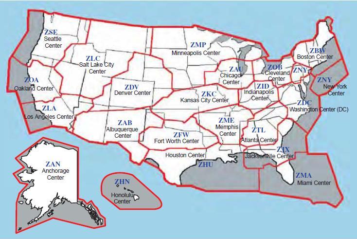
[Figure 3-1 Air Route Traffic Control Centers]
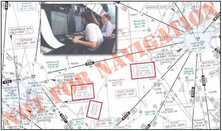
The CFRs require the pilot in command under IFR in controlled airspace to continuously monitor an appropriate Center or control frequency. When climbing after takeoff, an IFR flight is either in contact with a radarequipped local departure control or, in some areas, an ARTCC facility. As a flight transitions to the en route phase, pilots typically expect a handoff from departure control to a Center frequency if not already in contact with the Center. The FAA National Aeronautical Charting Office (NACO) publishes en route charts depicting Centers and sector frequencies, as shown in Figure 3-2 below.
[Figure 3-2 ARTCC Centers and Sector Frequencies]
During handoff from one Center to another, the previous controller assigns a new frequency. In cases where flights may be still out of range, the Center frequencies on the face of the chart are very helpful. In Figure 3-2, notice the boundary between Memphis and Atlanta Centers, and the remoted sites with discrete very high frequency (VHF) and ultra high frequency (UHF) for communicating with the appropriate ARTCC. These Center frequency boxes can be used for finding the nearest frequency within the aircraft range. They also can be used for making initial contact with the Center for clearances. The exact location for the Center transmitter is not shown, although the frequency box is placed as close as possible to the known location.
During the en route phase, as a flight transitions from one Center facility to the next, a handoff or transfer of control is required as previously described. The handoff procedure is similar to the handoff between other radar facilities, such as departure or approach control. During the handoff, the controller whose airspace is being vacated issues instructions that include the name of the facility to contact, appropriate frequency, and other pertinent remarks.
Accepting radar vectors from controllers does not relieve pilots of their responsibility for safety of flight. Pilots must maintain a safe altitude and keep track of their position, and it is their obligation to question controllers, request an amended clearance, or, in an emergency, deviate from their instructions if they believe that the safety of flight is in doubt. Keeping track of altitude and position when climbing, and during all other phases of flight, are basic elements of situational awareness. Aircraft equipped with an enhanced ground proximity warning system (EGPWS) or terrain awareness and warning system (TAWS) and traffic alert and collision avoidance system (TCAS) help pilots detect and correct unsafe altitudes and traffic conflicts. Regardless of equipment, pilots must always maintain situational awareness regarding their location and the location of traffic in their vicinity.
PREFERRED IFR ROUTES
A system of preferred IFR routes helps pilots, flight crews, and dispatchers plan a route of flight to minimize route changes, and to aid in the efficient, orderly management of air traffic using Federal airways. Preferred IFR routes are designed to serve the needs of airspace users and to provide for a systematic flow of air traffic in the major terminal and en route flight environments. Cooperation by all pilots in filing preferred routes results in fewer air traffic delays and better efficiency for departure, en route, and arrival air traffic service.
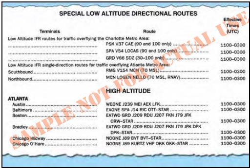
[Figure 3-3 Preferred IFR Routes]
Preferred IFR routes are published in the Airport/Facility Directory for the low and high altitude stratum. If they begin or end with an airway number, it indicates that the airway essentially overlies the airport and flights normally are cleared directly on the airway. Preferred IFR routes beginning or ending with a fix indicate that pilots may be routed to or from these fixes via a standard instrument departure (SID) route, radar vectors, or a standard terminal arrival route (STAR). Routes for major terminals are listed alphabetically under the name of the departure airport. Where several airports are in proximity they are listed under the principal airport and categorized as a metropolitan area; e.g., New York Metro Area. One way preferred IFR routes are listed numerically showing the segment fixes and the direction and times effective. Where more than one route is listed, the routes have equal priority for use. Official location identifiers are used in the route description for very high frequency omnidirectional ranges (VORs) and very high frequency omnidirectional ranges/tactical air navigation (VORTACs), and intersection names are spelled out. The route is direct where two NAVAIDs, an intersection and a NAVAID, a NAVAID and a NAVAID radial and distance point, or any navigable combination of these route descriptions follow in succession.
SUBSTITUTE EN ROUTE FLIGHT PROCEDURES
Air route traffic control centers are responsible for specifying essential substitute airway and route segments and fixes for use during VOR/VORTAC shutdowns. Scheduled shutdowns of navigational facilities require planning and coordination to ensure an uninterrupted flow of air traffic. A schedule of proposed facility shutdowns within the region is maintained and forwarded as far in advance as possible to enable the substitute routes to be published. Substitute routes are normally based on VOR/VORTAC facilities established and published for use in the appropriate altitude strata. In the case of substitute routes in the upper airspace stratum, it may be necessary to establish routes by reference to VOR/VORTAC facilities used in the low altitude system. Nondirectional radio beacon (NDB) facilities may only be used where VOR/VORTAC coverage is inadequate and ATC requirements necessitate use of such NAVAIDs. Where operational necessity dictates, navigational aids may be used beyond their standard service volume (SSV) limits, provided that the routes can be given adequate frequency protection.
The centerline of substitute routes must be contained within controlled airspace, although substitute routes for off-airway routes may not be in controlled airspace. Substitute routes are flight inspected to verify clearance of controlling obstacles and to check for satisfactory facility performance. To provide pilots with necessary lead time, the substitute routes are submitted in advance of the en route chart effective date. If the lead time cannot be provided, the shutdown may be delayed or a special graphic NOTAM may be considered. Normally, shutdown of facilities scheduled for 28 days (half the life of the en route chart) or less will not be charted. The format for describing substitute routes is from navigational fix to navigational fix. A minimum en route altitude (MEA) and a maximum authorized altitude (MAA) is provided for each route segment. Temporary reporting points may be substituted for the out-of-service facility and only those other reporting points that are essential for air traffic control. Normally, temporary reporting points over intersections are not necessary where Center radar coverage exists. A minimum reception altitude (MRA) is established for each temporary reporting point.
TOWER EN ROUTE CONTROL
Within the NAS it is possible to fly an IFR flight without leaving approach control airspace, using tower en route control (TEC) service. This helps expedite air traffic and reduces air traffic control and pilot communication requirements. TEC is referred to as “tower en route,” or “tower-to-tower,” and allows flight beneath the en route structure. Tower en route control reallocates airspace both vertically and geographically to allow flight planning between city pairs while remaining with approach control airspace. All users are encouraged to use the TEC route descriptions in the Airport/Facility Directory when filing flight plans. All published TEC routes are designed to avoid en route airspace, and the majority are within radar coverage.
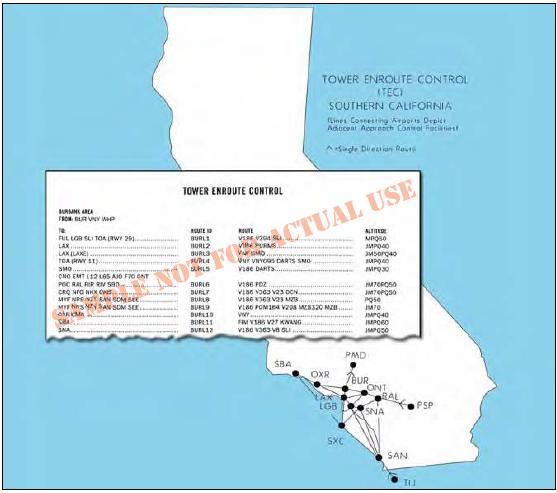
[Figure 3-4 Tower En Route Control]
The graphic depiction of TEC routes is not to be used for navigation or for detailed flight planning. Not all city pairs are depicted. It is intended to show geographic areas connected by tower en route control. Pilots should refer to route descriptions for specific flight planning. The word “DIRECT” appears as the route when radar vectors are used or no airway exists. Also, this indicates that a SID or STAR may be assigned by ATC. When a NAVAID or intersection identifier appears with no airway immediately preceding or following the identifier, the routing is understood to be direct to or from that point unless otherwise cleared by ATC. Routes beginning and ending with an airway indicate that the airway essentially overflies the airport, or radar vectors will be issued. Where more than one route is listed to the same destination, ensure that the correct route for the type of aircraft classification has been filed. These are denoted after the route in the altitude column using J (jet powered), M (turbo props/special, cruise speed 190 knots or greater), P (non-jet, cruise speed 190 knots or greater), or Q (non-jet, cruise speed 189 knots or less). Although all airports are not listed under the destination column, IFR flights may be planned to satellite airports in the proximity of major airports via the same routing. When filing flight plans, the coded route identifier, i.e., BURL1, VTUL4, or POML3, may be used in lieu of the route of flight.
AIRWAY AND ROUTE SYSTEM
The present en route system is based on the VHF airway/ route navigation system. Low frequency (LF) and integrated LF/VHF airways and routes have gradually been phased out in the conterminous U.S., with some remaining in Alaska.
MONITORING OF NAVIGATION FACILITIES
VOR, VORTAC, and instrument landing system (ILS) facilities, as well as most nondirectional radio beacons (NDBs) and marker beacons installed by the FAA, are provided with an internal monitoring feature. Internal monitoring is provided at the facility through the use of equipment that causes a facility shutdown if performance deteriorates below established tolerances. A remote status indicator also may be provided through the use of a signal-sampling receiver, microwave link, or telephone circuit. Older FAA NDBs and some non-Federal NDBs do not have the internal feature and monitoring is accomplished by manually checking the operation at least once each hour. FAA facilities such as automated flight service stations (AFSSs) and ARTCCs/sectors are usually the control point for NAVAID facility status. Pilots can query the appropriate FAA facility if they have questions in flight regarding NAVAID status, in addition to checking notices to airmen (NOTAMs) prior to flight, since NAVAIDs and associated monitoring equipment are continuously changing.
LF AIRWAYS/ROUTES
Numerous low frequency airways still exist in Alaska, as depicted in this NACO en route low altitude chart excerpt near Nome, Alaska.

[Figure 3-5 LF and VHF Airways — Alaska]
Colored LF east and west airways G7, G212 (green), and R35 (red), are shown, along with north and south airways B2, B27 (blue), and A1 (amber), all based upon the Fort Davis NDB en route NAVAID. The nearby Nome VORTAC VHF en route NAVAID is used with victor airways V452, V333, V507, V506, and V440.
VHF AIRWAYS/ROUTES
[Figure 3-6. VHF Jet Routes]
Figure 3-6 depicts numerous arrowed, single direction jet routes on this excerpt from a NACO en route high altitude chart, effective at and above 18,000 feet MSL up to and including FL 450. Notice the MAAs of 41,000 and 29,000 associated with J24 and J193, respectively. Additionally, note the BAATT, NAGGI, FUMES, and MEYRA area navigation (RNAV) waypoints. Waypoints are discussed in detail later in this chapter.
VHF EN ROUTE OBSTACLE CLEARANCE AREAS
All published routes in the NAS are based on specific obstacle clearance criteria. An understanding of en route obstacle clearance areas helps with situational awareness and may help avoid controlled flight into terrain (CFIT). Obstacle clearance areas for the en route phase of flight are identified as primary, secondary, and turning areas.
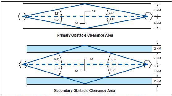
[Figure 3-7. VHF En Route Obstacle Clearance Areas]
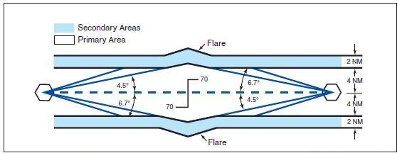
The primary and secondary area obstacle clearance criteria, airway and route widths, and the ATC separation procedures for en route segments are a function of safety and practicality in flight procedures. These flight procedures are dependent upon the pilot, the aircraft, and the navigation system being used, resulting in a total VOR system accuracy factor, along with an associated probability factor. The pilot/aircraft information component of these criteria includes pilot ability to track the radial and the flight track resulting from turns at various speeds and altitudes under different wind conditions. The navigation system information includes navigation facility radial alignment displacement, transmitter monitor tolerance, and receiver accuracy. All of these factors were considered during development of en route criteria. From this analysis, the computations resulted in a total system accuracy of ±4.5° 95 percent of the time and ±6.7° 99 percent of the time. The 4.5° figure became the basis for primary area obstacle clearance criteria, airway and route widths, and the ATC separation procedures. The 6.7° value provides secondary obstacle clearance area dimensions. Figure 3-7 depicts the primary and secondary obstacle clearance areas.
PRIMARY AREA
The primary obstacle clearance area has a protected width of 8 nautical miles (NM) with 4 NM on each side of the centerline. The primary area has widths of route protection based upon system accuracy of a ±4.5° angle from the NAVAID. These 4.5° lines extend out from the NAVAID and intersect the boundaries of the primary area at a point approximately 51 NM from the NAVAID. Ideally, the 51 NM point is where pilots would change over from navigating away from the facility, to navigating toward the next facility, although this ideal is rarely achieved.
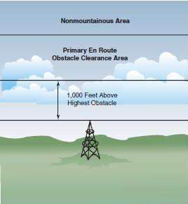
If the distance from the NAVAID to the changeover point (COP) is more than 51 NM, the outer boundary of the primary area extends beyond the 4 NM width along the 4.5° line when the COP is at midpoint. This means the primary area, along with its obstacle clearance criteria, is extended out into what would have been the secondary area. Additional differences in the obstacle clearance area result in the case of the effect of an offset COP or dogleg segment. For protected en route areas the minimum obstacle clearance in the primary area, not designated as mountainous under Part 95 — IFR altitude is 1,000 feet over the highest obstacle.
[Figure 3-8 Obstacle Clearance - Primary Area]
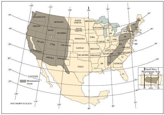
[Figure 3-9. Designated Mountainous Areas]
Mountainous areas for the Eastern and Western U.S. are designated in Part 95, as shown in Figure 3-9. Additional mountainous areas are designated for Alaska, Hawaii, and Puerto Rico. With some exceptions, the protected en route area minimum obstacle clearance over terrain and manmade obstacles in mountainous areas is 2,000 feet. Obstacle clearance is sometimes reduced to not less than 1,500 feet above terrain in the designated mountainous areas of the Eastern U.S., Puerto Rico, and Hawaii, and may be reduced to not less than 1,700 feet in mountainous areas of the Western U.S. and Alaska. Consideration is given to the following points before any altitudes providing less than 2,000 feet of terrain clearance are authorized:
• Areas characterized by precipitous terrain.
• Weather phenomena peculiar to the area.
• Phenomena conducive to marked pressure differentials.
• Type of and distance between navigational facilities.
• Availability of weather services throughout the area.
• Availability and reliability of altimeter resetting points along airways and routes in the area.
Altitudes providing at least 1,000 feet of obstacle clearance over towers and/or other manmade obstacles may be authorized within designated mountainous areas if the obstacles are not located on precipitous terrain where Bernoulli Effect is known or suspected to exist.
Bernoulli Effect, atmospheric eddies, vortices, waves, and other phenomena that occur in conjunction with disturbed airflow associated with the passage of strong winds over mountains can result in pressure deficiencies manifested as very steep horizontal pressure gradients. Since downdrafts and turbulence are prevalent under these conditions, potential hazards may be multiplied.
SECONDARY AREA
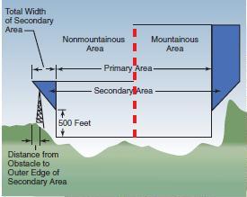
The secondary obstacle clearance area extends along a line 2 NM on each side of the primary area. Navigation system accuracy in the secondary area has widths of route protection of a ±6.7° angle from the NAVAID. These 6.7° lines intersect the outer boundaries of the secondary areas at the same point as primary lines, 51 NM from the NAVAID. If the distance from the NAVAID to the COP is more than 51 NM, the secondary area extends along the 6.7° line when the COP is at midpoint. In all areas, mountainous and nonmountainous, obstacles that are located in secondary areas are considered as obstacles to air navigation if they extend above the secondary obstacle clearance plane. This plane begins at a point 500 feet above the obstacles upon which the primary obstacle clearance area is based, and slants upward at an angle that causes it to intersect the outer edge of the secondary area at a point 500 feet higher.
[Figure 3-10 Obstacle Clearance - Secondary Area]
The obstacle clearance areas for LF airways and routes are different than VHF, with the primary and secondary area route widths both being 4.34 NM. The accuracy lines are 5.0° in the primary obstacle clearance area and 7.5° in the secondary area. Obstacle clearance in the primary area of LF airways and routes is the same as that required for VHF, although the secondary area obstacle clearance requirements are based upon distance from the facility and location of the obstacle relative to the inside boundary of the secondary area.
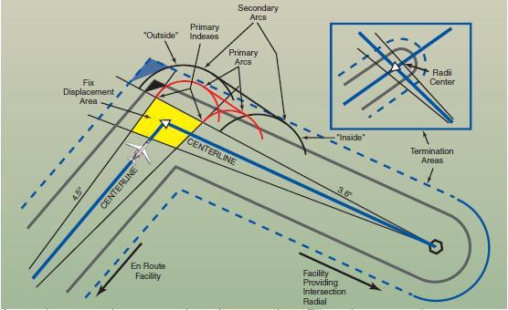
[Figure 3-11.Turning Area, Intersection Fix, NAVAID Distance less than 51 NM.]
When a VHF airway or route terminates at a NAVAID or fix, the primary area extends beyond that termination point. Figure 3-11 and its inset show the construction of the primary and secondary areas at the termination point. When a change of course on VHF airways and routes is necessary, the en route obstacle clearance turning area extends the primary and secondary obstacle clearance areas to accommodate the turn radius of the aircraft. Since turns at or after fix passage may exceed airway and route boundaries, pilots are expected to adhere to airway and route protected airspace by leading turns early before a fix. The turn area provides obstacle clearance for both turn anticipation (turning prior to the fix) and flyover protection (turning after crossing the fix). This does not violate the requirement to fly the centerline of the airway. Many factors enter into the construction and application of the turning area to provide pilots with adequate obstacle clearance protection. These may include aircraft speed, the amount of turn versus NAVAID distance, flight track, curve radii, MEAs, and minimum turning altitude (MTA). A typical protected airspace is shown in Figure 3-11. Turning area system accuracy factors must be applied to the most adverse displacement of the NAVAID or fix and the airway or route boundaries at which the turn is made. If applying nonmountainous en route turning area criteria graphically, depicting the vertical obstruction clearance in a typical application, the template might appear as in Figure 3-12.
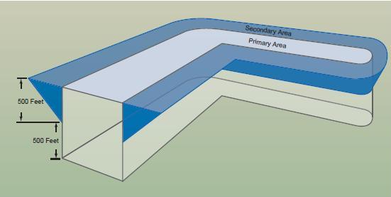
[Figure 3-12.Turning Area Obstruction Clearance]
Turns that begin at or after fix passage may exceed the protected en route turning area obstruction clearance.
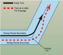
[Figure 3-13. Adhering to Airway/Route Turning Area]
Figure 3-13 contains an example of a flight track depicting a turn at or after fix passage, together with an example of an early turn. Without leading a turn, an aircraft operating in excess of 290 knots true airspeed (TAS) can exceed the normal airway or route boundaries depending on the amount of course change required, wind direction and velocity, the character of the turn fix (DME, overhead navigation aid, or intersection), and pilot technique in making a course change. For example, a flight operating at 17,000 feet MSL with a TAS of 400 knots, a 25° bank, and a course change of more than 40° would exceed the width of the airway or route; i.e., 4 NM each side of centerline. Due to the high airspeeds used at 18,000 feet MSL and above, additional IFR separation protection for course changes is provided.
NAVAID SERVICE VOLUME
Each class of VHF NAVAID (VOR/DME/TACAN) has an established operational service volume to ensure adequate signal coverage and frequency protection from other NAVAIDs on the same frequency. The maximum distance at which NAVAIDs are usable varies with altitude and the class of the facility. When using VORs for direct route navigation, the following guidelines apply:
• For operations above FL 450, use aids not more than 200 NM apart. These are High Altitude (H) class facilities and are depicted on en route high altitude charts.
• For operations that are off established airways from 18,000 feet MSL to FL 450, use aids not more than 260 NM apart. These are High Altitude (H) class facilities and are depicted on en route high altitude charts.
• For operations that are off established airways below 18,000 feet MSL, use aids not more than 80 NM apart. These are Low Altitude (L) class facilities and are shown on en route low altitude charts.
• For operations that are off established airways between 14,500 feet MSL and 17,999 feet MSL in the conterminous United States, use H-class facilities not more than 200 NM apart. The use of satellite based navigation systems has increased pilot requests for direct routes that take the aircraft outside ground based NAVAID service volume limits. These direct route requests are approved only in a radar environment, and approval is based on pilot responsibility for staying on the authorized direct route. ATC uses radar flight following for the purpose of aircraft separation. On the other hand, if ATC initiates a direct route that exceeds NAVAID service volume limits, ATC also provides radar navigational assistance as necessary. More information on direct route navigation is located in the En Route RNAV Procedures section later in this chapter.
NAVIGATIONAL GAPS
[Figure 3-14. Navigational Course Guidance Gaps]
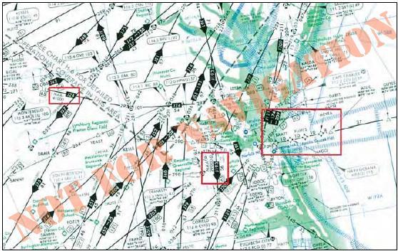
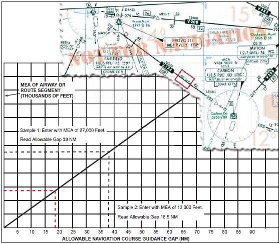
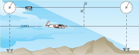
Where a navigational course guidance gap exists, referred to as an MEA gap, the airway or route segment may still be approved for navigation. The navigational gap may not exceed a specific distance that varies directly with altitude, from zero NM at sea level to 65 NM at 45,000 feet MSL and not more than one gap may exist in the airspace structure for the airway or route segment. Additionally, a gap usually does not occur at any airway or route turning point. To help ensure the maximum amount of continuous positive course guidance available when flying, there are established en route criteria for both straight and turning segments. Where large gaps exist that require altitude changes, MEA “steps” may be established at increments of not less than 2,000 feet below 18,000 feet MSL, or not less than 4,000 feet at 18,000 MSL and above, provided that a total gap does not exist for the entire segment within the airspace structure. MEA steps are limited to one step between any two facilities to eliminate continuous or repeated changes of altitude in problem areas. The allowable navigational gaps pilots can expect to see are determined, in part, by reference to the graph depicted in Figure 3-14. Notice the en route chart excerpt depicting that the MEA is established with a gap in navigation signal coverage northwest of the Carbon VOR/DME on V134. At the MEA of 13,000, the allowable navigation course guidance gap is approximately 18.5 NM, as depicted by Sample 2. The navigation gap area is not identified on the chart by distances from the navigation facilities.
CHANGEOVER POINTS
[Figure 3-15. Changeover Points]
When flying airways, pilots normally change frequencies midway between navigation aids, although there are times when this is not practical. If the navigation signals cannot be received from the second VOR at the midpoint of the route, a changeover point (COP) is depicted and shows the distance in NM to each NAVAID, as depicted in Figure 3-15. COPs indicate the point where a frequency change is necessary to receive course guidance from the facility ahead of the aircraft instead of the one behind. These changeover points divide an airway or route segment and ensure continuous reception of navigation signals at the prescribed minimum en route IFR altitude. They also ensure that other aircraft operating within the same portion of an airway or route segment receive consistent azimuth signals from the same navigation facilities regardless of the direction of flight.
[Figure 3-16. Changeover Point Effect on Long Airway or Route Segment]
Where signal coverage from two VORs overlaps at the MEA, the changeover point normally is designated at the midpoint. Where radio frequency interference or other navigation signal problems exist, the COP is placed at the optimum location, taking into consideration the signal strength, alignment error, or any other known condition that affects reception. The changeover point has an effect on the primary and secondary obstacle clearance areas. On long airway or route segments, if the distance between two facilities is over 102 NM and the changeover point is placed at the midpoint, the system accuracy lines extend beyond the minimum widths of 8 and 12 NM, and a flare or spreading outward results at the COP, as shown in Figure 3-16. Offset changeover points and dogleg segments on airways or routes can also result in a flare at the COP.
IFR EN ROUTE ALTITUDES
Minimum en route altitudes, minimum reception altitudes, maximum authorized altitudes, minimum obstruction clearance altitudes, minimum crossing altitudes, and changeover points are established by the FAA for instrument flight along Federal airways, as well as some off-airway routes. The altitudes are established after it has been determined that the navigation aids to be used are adequate and so oriented on the airways or routes that signal coverage is acceptable, and that flight can be maintained within prescribed route widths.
For IFR operations, regulations require that pilots operate their aircraft at or above minimum altitudes. Except when necessary for takeoff or landing, pilots may not operate an aircraft under IFR below applicable minimum altitudes, or if no applicable minimum altitude is prescribed, in the case of operations over an area designated as mountainous, an altitude of 2,000 feet above the highest obstacle within a horizontal distance of 4 NM from the course to be flown. In any other case, an altitude of 1,000 feet above the highest obstacle within a horizontal distance of 4 NM from the course to be flown must be maintained as a minimum altitude. If both a MEA and a minimum obstruction clearance altitude (MOCA) are prescribed for a particular route or route segment, pilots may operate an aircraft below the MEA down to, but not below, the MOCA, only when within 22 NM of the VOR. When climbing to a higher minimum IFR altitude (MIA), pilots must begin climbing immediately after passing the point beyond which that minimum altitude applies, except when ground obstructions intervene, the point beyond which that higher minimum altitude applies must be crossed at or above the applicable minimum crossing altitude (MCA) for the VOR.
If on an IFR flight plan, but cleared by ATC to maintain VFR conditions on top, pilots may not fly below minimum en route IFR altitudes. Minimum altitude rules are designed to ensure safe vertical separation between the aircraft and the terrain. These minimum altitude rules apply to all IFR flights, whether in IFR or VFR weather conditions, and whether assigned a specific altitude or VFR conditions on top.
MINIMUM EN ROUTE ALTITUDE
The minimum enroute altitude (MEA) is the lowest published altitude between radio fixes that assures acceptable navigational signal coverage and meets obstacle clearance requirements between those fixes. The MEA prescribed for a Federal airway or segment, RNAV low or high route, or other direct route applies to the entire width of the airway, segment, or route between the radio fixes defining the airway, segment, or route. MEAs for routes wholly contained within controlled airspace normally provide a buffer above the floor of controlled airspace consisting of at least 300 feet within transition areas and 500 feet within control areas. MEAs are established based upon obstacle clearance over terrain and manmade objects, adequacy of navigation facility performance, and communications requirements, although adequate communication at the MEA is not guaranteed.
MINIMUM OBSTRUCTION CLEARANCE ALTITUDE
The minimum obstruction clearance altitude (MOCA) is the lowest published altitude in effect between fixes on VOR airways, off-airway routes, or route segments that meets obstacle clearance requirements for the entire route segment. This altitude also assures acceptable navigational signal coverage only within 22 NM of a VOR. The MOCA seen on the NACO en route chart, may have been computed by adding the required obstacle clearance (ROC) to the controlling obstacle in the primary area or computed by using a TERPS chart if the controlling obstacle is located in the secondary area. This figure is then rounded to the nearest 100 - foot increment, i.e., 2,049 feet becomes 2,000, and 2,050 feet becomes 2,100 feet. An extra 1,000 feet is added in mountainous areas, in most cases. The MOCA is based upon obstacle clearance over the terrain or over manmade objects, adequacy of navigation facility performance, and communications requirements.
ATC controllers have an important role in helping pilots remain clear of obstructions. Controllers are instructed to issue a safety alert if the aircraft is in a position that, in their judgment, places the pilot in unsafe proximity to terrain, obstructions, or other aircraft. Once pilots inform ATC of action being taken to resolve the situation, the controller may discontinue the issuance of further alerts. A typical terrain/obstruction alert may sound like this: “Low altitude alert. Check your altitude immediately. The MOCA in your area is 12,000.”
MINIMUM VECTORING ALTITUDES
Minimum vectoring altitudes (MVAs) are established for use by ATC when radar ATC is exercised. The MVA provides 1,000 feet of clearance above the highest obstacle in nonmountainous areas and 2,000 feet above the highest obstacle in designated mountainous areas. Because of the ability to isolate specific obstacles, some MVAs may be lower than MEAs, MOCAs, or other minimum altitudes depicted on charts for a given location. While being radar vectored, IFR altitude assignments by ATC are normally at or above the MVA.
Controllers use MVAs only when they are assured an adequate radar return is being received from the aircraft. Charts depicting minimum vectoring altitudes are normally available to controllers but not available to pilots. Situational awareness is always important, especially when being radar vectored during a climb into an area with progressively higher MVA sectors, similar to the concept of minimum crossing altitude. Except where diverse vector areas have been established, when climbing, pilots should not be vectored into a sector with a higher MVA unless at or above the next sector’s MVA. Where lower MVAs are required in designated mountainous areas to achieve compatibility with terminal routes or to permit vectoring to an instrument approach procedure, 1,000 feet of obstacle clearance may be authorized with the use of Airport Surveillance Radar (ASR). The MVA will provide at least 300 feet above the floor of controlled airspace. The MVA charts are developed to the maximum radar range. Sectors provide separation from terrain and obstructions. Each MVA chart has sectors large enough to accommodate vectoring of aircraft within the sector at the MVA.
[Figure 3-17. Example of an Air Route Traffic Control Center MVA Chart]
MINIMUM RECEPTION ALTITUDE
Minimum reception altitudes (MRAs) are determined by FAA flight inspection traversing an entire route of flight to establish the minimum altitude the navigation signal can be received for the route and for off-course NAVAID facilities that determine a fix. When the MRA at the fix is higher than the MEA, an MRA is established for the fix, and is the lowest altitude at which an intersection can be determined.
MINIMUM CROSSING ALTITUDE
[Figure 3-18. Minimum Crossing Altitude]
A minimum crossing altitude (MCA) is the lowest altitude at certain fixes at which the aircraft must cross when proceeding in the direction of a higher minimum en route IFR altitude, as depicted in Figure 3-18. MCAs are established in all cases where obstacles intervene to prevent pilots from maintaining obstacle clearance during a normal climb to a higher MEA after passing a point beyond which the higher MEA applies. The same protected en route area vertical obstacle clearance requirements for the primary and secondary areas are considered in the determination of the MCA. The standard for determining the MCA is based upon the following climb gradients, and is computed from the flight altitude:
• Sea level through 5,000 feet MSL—150 feet per NM
• 5000 feet through 10,000 feet MSL — 120 feet per NM
• 10,000 feet MSL and over — 100 feet per NM
[Figure 3-19. MCA Determination Point.]
To determine the MCA seen on a NACO en route chart, the distance from the obstacle to the fix is computed from the point where the centerline of the en route course in the direction of flight intersects the farthest displacement from the fix, as shown in Figure 3-19. When a change of altitude is involved with a course change, course guidance must be provided if the change of altitude is more than 1,500 feet and/or if the course change is more than 45 degrees, although there is an exception to this rule. In some cases, course changes of up to 90 degrees may be approved without course guidance provided that no obstacles penetrate the established MEA requirement of the previous airway or route segment. Outside U. S. airspace, pilots may encounter different flight procedures regarding MCA and transitioning from one MEA to a higher MEA. In this case, pilots are expected to be at the higher MEA crossing the fix, similar to an MCA. Pilots must thoroughly review flight procedure differences when flying outside U.S. airspace. On NACO en route charts, routes and associated data outside the conterminous U.S. are shown for transitional purposes only and are not part of the high altitude jet route and RNAV route systems.
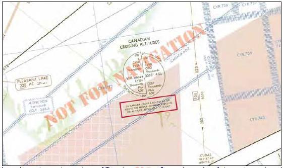
[Figure 3-20 Crossing a Fix to a Higher MEA in Canada]
MAXIMUM AUTHORIZED ALTITUDE
A maximum authorized altitude (MAA) is a published altitude representing the maximum usable altitude or flight level for an airspace structure or route segment. It is the highest altitude on a Federal airway, jet route, RNAV low or high route, or other direct route for which an MEA is designated at which adequate reception of navigation signals is assured. MAAs represent procedural limits determined by technical limitations or other factors such as limited airspace or frequency interference of ground based facilities.
IFR CRUISING ALTITUDE OR FLIGHT LEVEL
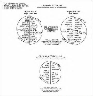
In controlled airspace, pilots must maintain the altitude or flight level assigned by ATC, although if the ATC clearance assigns “VFR conditions on-top,” an altitude or flight level as prescribed by Part 91.159 must be maintained. In uncontrolled airspace (except while in a holding pattern of 2 minutes or less or while turning) if operating an aircraft under IFR in level cruising flight, an appropriate altitude as depicted in the legend of NACO IFR en route high and low altitude charts must be maintained.
[Figure 3-21 IFR Cruising Altitude or Flight Level]
When operating on an IFR flight plan below 18,000 feet MSL in accordance with a VFR-on-top clearance, any VFR cruising altitude appropriate to the direction of flight between the MEA and 18,000 feet MSL may be selected that allows the flight to remain in VFR conditions. Any change in altitude must be reported to ATC and pilots must comply with all other IFR reporting procedures. VFR-on-top is not authorized in Class A airspace. When cruising below 18,000 feet MSL, the altimeter must be adjusted to the current setting, as reported by a station within 100 NM of your position. In areas where weather-reporting stations are more than 100 NM from the route, the altimeter setting of a station that is closest may be used. During IFR flight, ATC advises flights periodically of the current altimeter setting, but it remains the responsibility of the pilot or flight crew to update altimeter settings in a timely manner. Altimeter settings and weather information are available from weather reporting facilities operated or approved by the U.S. National Weather Service, or a source approved by the FAA. Some commercial operators have the authority to act as a government-approved source of weather information, including altimeter settings, through certification under the FAA’s Enhanced Weather Information System.
Flight level operations at or above 18,000 feet MSL require the altimeter to be set to 29.92. A flight level (FL) is defined as a level of constant atmospheric pressure related to a reference datum of 29.92 in. Hg. Each flight level is stated in three digits that represent hundreds of feet. For example, FL 250 represents an altimeter indication of 25,000 feet. Conflicts with traffic operating below 18,000 feet MSL may arise when actual altimeter settings along the route of flight are lower than 29.92. Therefore, Part 91.121 specifies the lowest usable flight levels for a given altimeter setting range.
LOWEST USABLE FLIGHT LEVEL
When the barometric pressure is 31.00 inches of mercury or less and pilots are flying below 18,000 feet MSL, use the current reported altimeter setting. This is important because the true altitude of an aircraft is lower than indicated when sea level pressure is lower than standard. When an aircraft is en route on an instrument flight plan, air traffic controllers furnish this information at least once while the aircraft is in the controller’s area of jurisdiction. According to Part 91.144, when the barometric pressure exceeds 31.00 inches Hg., the following procedures are placed in effect by NOTAM defining the geographic area affected: Set 31.00 inches for en route operations below 18,000 feet MSL and maintain this setting until beyond the affected area. Air traffic control issues actual altimeter settings and advises pilots to set 31.00 inches in their altimeter, for en route operations below 18,000 feet MSL in affected areas. If an aircraft has the capability of setting the current altimeter setting and operating into airports with the capability of measuring the current altimeter setting, no additional restrictions apply. At or above 18,000 feet MSL, altimeters should be set to 29.92 inches of mercury (standard setting). Additional procedures exist beyond the en route phase of flight.
The lowest usable flight level is determined by the atmospheric pressure in the area of operation. As local altimeter settings fall below 29.92, pilots operating in Class A airspace must cruise at progressively higher indicated altitudes to ensure separation from aircraft operating in the low altitude structure as follows:
Current Altimeter Setting Lowest Usable Flight Level
• 29.92 or higher 180
• 29.91 to 29.42 185
• 29.41 to 28.92 190
• 28.91 to 28.42 195
• 28.41 to 27.92 200
When the minimum altitude, as prescribed in Parts 91.159 and 91.177, is above 18,000 feet MSL, the lowest usable flight level is the flight level equivalent of the minimum altitude plus the number of feet specified according to the lowest flight level correction factor as follows:
Altimeter Setting Correction Factor
• 29.92 or higher none
• 29.91 to 29.42 500 Feet
• 29.41 to 28.92 1000 Feet
• 28.91 to 28.42 1500 Feet
• 28.41 to 27.92 2000 Feet
• 27.91 to 27.42 2500 Feet
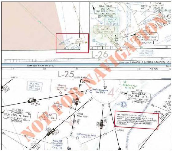
OPERATIONS IN OTHER COUNTRIES
[Figure 3-22. Altimeter Setting Changes]
When flight crews transition from the U.S. NAS to another country’s airspace, they should be aware of differences not only in procedures but also airspace. For example, when flying into Canada regarding altimeter setting changes, as depicted in Figure 3-22, notice the change from QNE to QNH when flying northbound into the Moncton flight information region (FIR), an airspace of defined dimensions where flight information service and alerting service are provided. Transition altitude (QNH) is the altitude in the vicinity of an airport at or below which the vertical position of the aircraft is controlled by reference to altitudes (MSL). The transition level (QNE) is the lowest flight level available for use above the transition altitude. Transition height (QFE) is the height in the vicinity of an airport at or below which the vertical position of the aircraft is expressed in height above the airport reference datum. The transition layer is the airspace between the transition altitude and the transition level. If descending through the transition layer, set the altimeter to local station pressure. When departing and climbing through the transition layer, use the standard altimeter setting (QNE) of 29.92 inches of Mercury, 1013.2 millibars, or 1013.2 hectopascals. Remember that most pressure altimeters are subject to mechanical, elastic, temperature, and installation errors. Extreme cold temperature differences also may require a correction factor.
REPORTING PROCEDURES
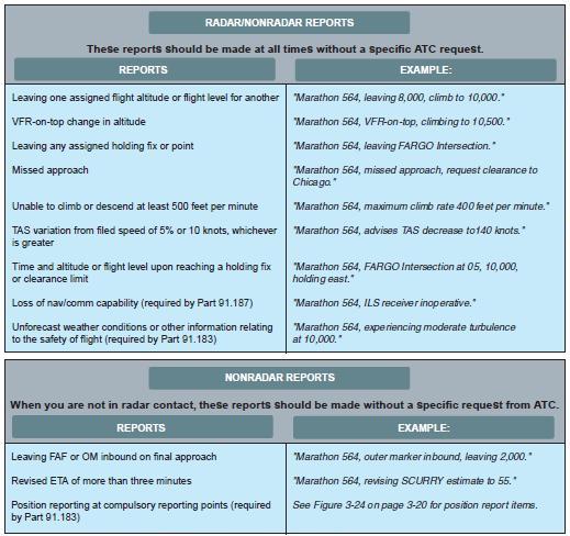
[Figure 3-23. ATC Reporting Procedure Examples]
In addition to acknowledging a handoff to another Center en route controller, there are reports that should be made without a specific request from ATC. Certain reports should be made at all times regardless of whether a flight is in radar contact with ATC, while others are necessary only if radar contact has been lost or terminated. Refer to Figure 3-23 for a review of these reports.
NONRADAR POSITION REPORTS
If radar contact has been lost or radar service terminated, the CFRs require pilots to provide ATC with position reports over designated VORs and intersections along their route of flight. These compulsory reporting points are depicted on NACO IFR en route charts by solid triangles. Position reports over fixes indicated by open triangles are noncompulsory reporting points, and are only necessary when requested by ATC. If on a direct course that is not on an established airway, report over the fixes used in the flight plan that define the route, since they automatically become compulsory reporting points. Compulsory reporting points also apply when conducting an IFR flight in accordance with a VFR-on-top clearance. Whether a route is on airways or direct, position reports are mandatory in a nonradar environment, and they must include specific information. A typical position report includes information pertaining to aircraft position, expected route, and estimated time of arrival (ETA). Time may be stated in minutes only when no misunderstanding is likely to occur.
[Figure 3-23. ATC Reporting Procedure Examples]
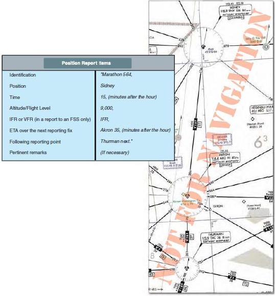
[Figure 3-24. Nonradar Position Reports]
COMMUNICATION FAILURE
Two-way radio communication failure procedures for IFR operations are outlined in Part 91.185. Unless otherwise authorized by ATC, pilots operating under IFR are expected to comply with this regulation. Expanded procedures for communication failures are found in the AIM. Pilots can use the transponder to alert ATC to a radio communication failure by squawking code 7600.
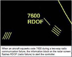
[Figure 3-25 Two-Way Radio Communication Failure
Transponder Code]
If only the transmitter is inoperative, listen for ATC instructions on any operational receiver, including the navigation receivers. It is possible ATC may try to make contact with pilots over a VOR, VORTAC, NDB, or localizer frequency. In addition to monitoring NAVAID receivers, attempt to reestablish communications by contacting ATC on a previously assigned frequency, calling a FSS or Aeronautical Radio Incorporated (ARINC).
The primary objective of the regulations governing communication failures is to preclude extended IFR no-radio operations within the ATC system since these operations may adversely affect other users of the airspace. If the radio fails while operating on an IFR clearance, but in VFR conditions, or if encountering VFR conditions at any time after the failure, continue the flight under VFR conditions, if possible, and land as soon as practicable. The requirement to land as soon as practicable should not be construed to mean as soon as possible. Pilots retain the prerogative of exercising their best judgment and are not required to land at an unauthorized airport, at an airport unsuitable for the type of aircraft flown, or to land only minutes short of their intended destination. However, if IFR conditions prevail, pilots must comply with procedures designated in the CFRs to ensure aircraft separation.
If pilots must continue their flight under IFR after experiencing two-way radio communication failure, they should fly one of the following routes:
• The route assigned by ATC in the last clearance received.
• If being radar vectored, the direct route from the point of radio failure to the fix, route, or airway specified in the radar vector clearance.
• In the absence of an assigned route, the route ATC has advised to expect in a further clearance.
• In the absence of an assigned or expected route, the route filed in the flight plan.
It is also important to fly a specific altitude should two-way radio communications be lost. The altitude to fly after a communication failure can be found in Part 91.185 and must be the highest of the following altitudes for each route segment flown.
• The altitude or flight level assigned in the last ATC clearance.
• The minimum altitude or flight level for IFR operations.
• The altitude or flight level ATC has advised to expect in a further clearance.
In some cases, the assigned or expected altitude may not be as high as the MEA on the next route segment. In this situation, pilots normally begin a climb to the higher MEA when they reach the fix where the MEA rises. If the fix also has a published minimum crossing altitude, they start the climb so they will be at or above the MCA when reaching the fix. If the next succeeding route segment has a lower MEA, descend to the applicable altitude - either the last assigned altitude or the altitude expected in a further clearance - when reaching the fix where the MEA decreases.
CLIMBING AND DESCENDING EN ROUTE
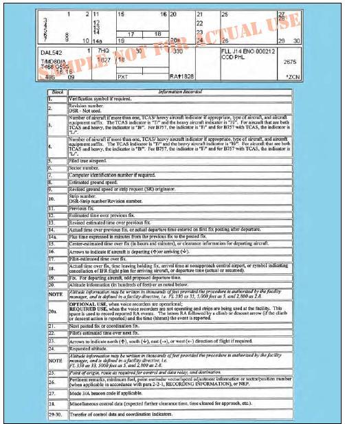
[Figure 3-26. En Route Flight Progress Strip and Data Entries]
Before the days of nationwide radar coverage, en route aircraft were separated from each other primarily by specific altitude assignments and position reporting procedures. Much of the pilot’s time was devoted to inflight calculations, revising ETAs, and relaying position reports to ATC. Today, pilots and air traffic controllers have far more information and better tools to make inflight computations and, with the expansion of radar, including the use of an en route flight progress strip shown in Figure 3-26, position reports may only be necessary as a backup in case of radar failure or for RNAV random route navigation. Figure 3-26 also depicts the numerous en route data entries used on a flight progress strip, generated by the ARTCC computer. Climbing, level flight, and descending during the en route phase of IFR flight involves staying in communication with ATC, making necessary reports, responding to clearances, monitoring position, and staying abreast of any changes to the airplane’s equipment status or weather.
PILOT/CONTROLLER EXPECTATIONS
When ATC issues a clearance or instruction, pilots are expected to execute its provisions upon receipt. In some cases, ATC includes words that modify their expectation. For example, the word “immediately” in a clearance or instruction is used to impress urgency to avoid an imminent situation, and expeditious compliance is expected and necessary for safety. The addition of a climb point or time restriction, for example, does not authorize pilots to deviate from the route of flight or any other provision of the ATC clearance. If you receive a term “climb at pilot’s discretion” in the altitude information of an ATC clearance, it means that you have the option to start a climb when you wish, that you are authorized to climb at any rate, and to temporarily level off at any intermediate altitude as desired, although once you vacate an altitude, you may not return to that altitude. When ATC has not used the term “at pilot’s discretion” nor imposed any climb restrictions, you should climb promptly on acknowledgment of the clearance. Climb at an optimum rate consistent with the operating characteristics of your aircraft to 1,000 feet below the assigned altitude, and then attempt to climb at a rate between 500 and 1,500 feet per minute until you reach your assigned altitude. If at anytime you are unable to climb at a rate of at least 500 feet a minute, advise ATC. If it is necessary to level off at an intermediate altitude during climb, advise ATC.
“Expedite climb” normally indicates you should use the approximate best rate of climb without an exceptional change in aircraft handling characteristics. Normally controllers will inform you of the reason for an instruction to expedite. If you fly a turbojet airplane equipped with afterburner engines, such as a military aircraft, you should advise ATC prior to takeoff if you intend to use afterburning during your climb to the en route altitude. Often, the controller may be able to plan traffic to accommodate a high performance climb and allow you to climb to the planned altitude without restriction. If you receive an “expedite” clearance from ATC, and your altitude to maintain is subsequently changed or restated without an expedite instruction, the expedite instruction is canceled.
During en route climb, as in any other phase of flight, it is essential that you clearly communicate with ATC regarding clearances. In the following example, a flight crew experienced an apparent clearance readback/hearback error, that resulted in confusion about the clearance, and ultimately, to inadequate separation from another aircraft. “Departing IFR, clearance was to maintain 5,000 feet, expect 12,000 in ten minutes. After handoff to Center, we understood and read back, ‘Leaving 5,000 turn left heading 240° for vector on course.’ The First Officer turned to the assigned heading climbing through 5,000 feet. At 5,300 feet Center advised assigned altitude was 5,000 feet. We immediately descended to 5,000. Center then informed us we had traffic at 12 o’clock and a mile at 6,000. After passing traffic, a higher altitude was assigned and climb resumed. We now believe the clearance was probably ‘reaching’ 5,000, etc. Even our readback to the controller with ‘leaving’ didn’t catch the different wording.” “Reaching” and “leaving” are commonly used ATC terms having different usages. They may be used in clearances involving climbs, descents, turns, or speed changes. In the cockpit, the words “reaching” and “leaving” sound much alike.
For altitude awareness during climb, professional pilots often call out altitudes on the flight deck. The pilot monitoring may call 2,000 and 1,000 feet prior to reaching an assigned altitude. The callout may be, “two to go” and “one to go.” Climbing through the transition altitude (QNH), both pilots set their altimeters to 29.92 inches of mercury and announce “2992 inches” (or ‘standard,’ on some airplanes) and the flight level passing. For example, “2992 inches” (‘standard’), flight level one eight zero.” The second officer on three pilot crews may ensure that both pilots have inserted the proper altimeter setting. On international flights, pilots must be prepared to differentiate, if necessary, between barometric pressure equivalents with inches of mercury, and millibars or hectopascals, to eliminate any potential for error, for example, 996 millibars erroneously being set as 2996.
For a typical IFR flight, the majority of inflight time often is flown in level flight at cruising altitude, from top of climb to top of descent (TOD). Generally, TOD is used in airplanes with a flight management system (FMS), and represents the point at which descent is first initiated from cruise altitude. FMSs also assist in level flight by cruising at the most fuel saving speed, providing continuing guidance along the flight plan route, including great circle direct routes, and continuous evaluation and prediction of fuel consumption along with changing clearance data. Descent planning is discussed in more detail in the next chapter, “Arrivals.”
AIRCRAFT SPEED AND ALTITUDE
During the en route descent phase of flight, an additional benefit of flight management systems is that the FMS provides fuel saving idle thrust descent to your destination airport. This allows an uninterrupted profile descent from level cruising altitude to an appropriate minimum IFR altitude (MIA), except where level flight is required for speed adjustment. Controllers anticipate and plan that you may level off at 10,000 feet MSL on descent to comply with the Part 91 indicated airspeed limit of 250 knots. Leveling off at any other time on descent may seriously affect air traffic handling by ATC. It is imperative that you make every effort to fulfill ATC expected actions on descent to aid in safely handling and expediting air traffic.
ATC issues speed adjustments if you are being radar controlled to achieve or maintain required or desired spacing. They express speed adjustments in terms of knots based on indicated airspeed in 10 knot increments except that at or above FL 240 speeds may be expressed in terms of Mach numbers in 0.01 increments. The use of Mach numbers by ATC is restricted to turbojets. If complying with speed adjustments, pilots are expected to maintain that speed within plus or minus 10 knots or 0.02 Mach.
Speed and altitude restrictions in clearances are subject to misinterpretation, as evidenced in this case where a corporate flight crew treated instructions in a published procedure as a clearance. “…We were at FL 310 and had already programmed the ‘expect-crossing altitude’ 3-23 of 17,000 feet at the VOR. When the altitude alerter sounded, I advised Center that we were leaving FL 310. ATC acknowledged with a ‘Roger.’ At FL 270, Center quizzed us about our descent. I told the controller we were descending so as to cross the VOR at 17,000 feet. ATC advised us that we did not have clearance to descend. What we thought was a clearance was in fact an ‘expect’ clearance. We are both experienced pilots…which just means that experience is no substitute for a direct question to Center when you are in doubt about a clearance. Also, the term ‘Roger’ only means that ATC received the transmission, not that they understood the transmission. The AIM indicates that ‘expect’ altitudes are published for planning purposes. ‘Expect’ altitudes are not considered crossing restrictions until verbally issued by ATC.”
HOLDING PROCEDURES
The criteria for holding pattern airspace is developed both to provide separation of aircraft, as well as obstacle clearance The alignment of holding patterns typically coincides with the flight course you fly after leaving the holding fix. For level holding, a minimum of 1,000 feet obstacle clearance is provided throughout the primary area. In the secondary area 500 feet of obstacle clearance is provided at the inner edge, tapering to zero feet at the outer edge. Allowance for precipitous terrain is considered, and the altitudes selected for obstacle clearance may be rounded to the nearest 100 feet. When criteria for a climb in hold are applied, no obstacle penetrates the holding surface.
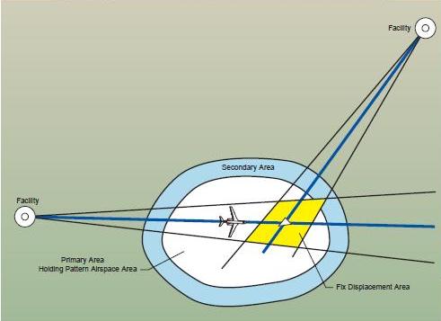
[Figure 3-27 Typical Holding Pattern Design Criteria Template]
There are many factors that affect aircraft during holding maneuvers, including navigational aid ground and airborne tolerance, effect of wind, flight procedures, application of air traffic control, outbound leg length, maximum holding airspeeds, fix to NAVAID distance, DME slant range effect, holding airspace size, and altitude holding levels. In order to allow for these factors when establishing holding patterns, procedure specialists must apply complex criteria contained in Order 7130.3, Holding Pattern Criteria.
ATC HOLDING INSTRUCTIONS
When controllers anticipate a delay at a clearance limit or fix, pilots will usually be issued a holding clearance at least five minutes before the ETA at the clearance limit or fix. If the holding pattern assigned by ATC is depicted on the appropriate aeronautical chart, pilots are expected to hold as published. In this situation, the controller will issue a holding clearance which includes the name of the fix, directs you to hold as published, and includes an expect further clearance (EFC) time. An example of such a clearance is: “Marathon five sixty four, hold east of MIKEY Intersection as published, expect further clearance at 1521.” When ATC issues a clearance requiring you to hold at a fix where a holding pattern is not charted, you will be issued complete holding instructions. This information includes the direction from the fix, name of the fix, course, leg length, if appropriate, direction of turns (if left turns are required), and the EFC time. You are required to maintain your last assigned altitude unless a new altitude is specifically included in the holding clearance, and you should fly right turns unless left turns are assigned. Note that all holding instructions should include an EFC time. If you lose two-way radio communication, the EFC allows you to depart the holding fix at a definite time. Plan the last lap of your holding pattern to leave the fix as close as possible to the exact time.
[Figure 3-28 ATC Holding Instructions]
If you are approaching your clearance limit and have not received holding instructions from ATC, you are expected to follow certain procedures. First, call ATC and request further clearance before you reach the fix. If you cannot obtain further clearance, you are expected to hold at the fix in compliance with the published holding pattern. If a holding pattern is not charted at the fix, you are expected to hold on the inbound course using right turns. This procedure ensures that ATC will provide adequate separation.
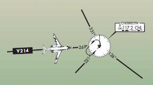
[Figure 3-29 Clearance Limit Holding]
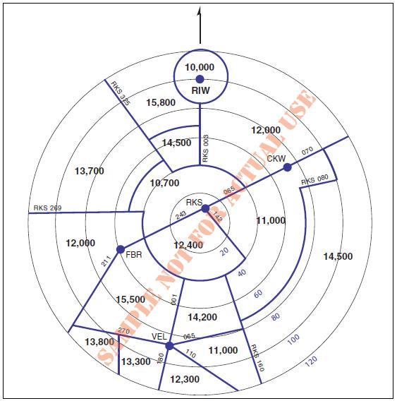
Assume you are eastbound on V214 and the Cherrelyn VORTAC is your clearance limit. If you have not been able to obtain further clearance and have not received holding instructions, you should plan to hold southwest on the 221 degrees radial using left-hand turns, as depicted. If this holding pattern was not charted, you would hold west of the VOR on V214 using right-hand turns. Where required for aircraft separation, ATC may request that you hold at any designated reporting point in a standard holding pattern at the MEA or the MRA, whichever altitude is the higher at locations where a minimum holding altitude has not been established. Unplanned holding at en route fixes may be expected on airway or route radials, bearings, or courses. If the fix is a facility, unplanned holding could be on any radial or bearing. There may be holding limitations required if standard holding cannot be accomplished at the MEA or MRA.
MAXIMUM HOLDING SPEED
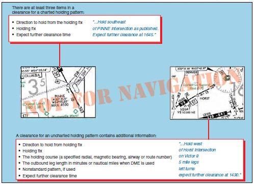
As you have seen, the size of the holding pattern is directly proportional to the speed of the airplane. In order to limit the amount of airspace that must be protected by ATC, maximum holding speeds in knots. A clearance for an uncharted holding pattern contains additional information: There are at least three items in a clearance for a charted holding pattern:
• Direction to hold from the holding fix
• Holding fix
• Expect further clearance time "...Hold southeast of PINNE Intersection as published. Expect further clearance at 1645."
• Direction to hold from holding fix
• Holding fix
• The holding course (a specified radial, magnetic bearing, airway or route number)
• The outbound leg length in minutes or nautical miles when DME is used
• Nonstandard pattern, if used
• Expect further clearance time "...Hold west of Horst Intersection on Victor 8 5 mile legs left turns expect further clearance at 1430." 3-25 indicated airspeed (KIAS) have been designated for specific altitude ranges
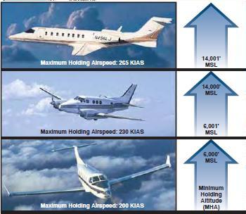
[Figure 3-30 Maximum Holding Speed Examples.]
Even so, some holding patterns may have additional speed restrictions to keep faster airplanes from flying out of the protected area. If a holding pattern has a nonstandard speed restriction, it will be depicted by an icon with the limiting airspeed. If the holding speed limit is less than you feel is necessary, you should advise ATC of your revised holding speed. Also, if your indicated airspeed exceeds the applicable maximum holding speed, ATC expects you to slow to the speed limit within three minutes of your ETA at the holding fix. Often pilots can avoid flying a holding pattern, or reduce the length of time spent in the holding pattern, by slowing down on the way to the holding fix.
HIGH PERFORMANCE HOLDING
Certain limitations come into play when you operate at higher speeds; for instance, aircraft do not make standard rate turns in holding patterns if the bank angle will exceed 30 degrees. If your aircraft is using a flight director system, the bank angle is limited to 25 degrees. Since any aircraft must be traveling at over 210 knots TAS for the bank angle in a standard rate turn to exceed 30 degrees, this limit applies to relatively fast airplanes. An aircraft using a flight director would have to be holding at more than 170 knots TAS to come up against the 25 degrees limit. These true airspeeds correspond to indicated airspeeds of about 183 and 156 knots, respectively, at 6,000 feet in a standard atmosphere
[Figure 3-31 High Performance Holding].
Since some military airplanes need to hold at higher speeds than the civilian limits, the maximum at military airfields is higher. For example, the maximum holding airspeed at USAF airfields is 310 KIAS.
FUEL STATE AWARENESS
In order to increase fuel state awareness, commercial operators and other professional flight crews are required to record the time and fuel remaining during IFR flight. For example, on a flight scheduled for one hour or less, the flight crew may record the time and fuel remaining at the top of climb (TOC) and at one additional waypoint listed in the flight plan. Generally, TOC is used in airplanes with a flight management system, and represents the point at which cruise altitude is first reached. TOC is calculated based on current airplane altitude, climb speed, and cruise altitude. The captain may elect to delete the additional waypoint recording requirement if the flight is so short that the record will not assist in the management of the flight. For flights scheduled for more than one hour, the flight crew may record the time and fuel remaining shortly after the top of climb and at selected waypoints listed in the flight plan, conveniently spaced approximately one hour apart. The flight crew compares actual fuel burn to planned fuel burn. Each fuel tank must be monitored to verify proper burn off and appropriate fuel remaining. On two pilot airplanes, the pilot monitoring (PM) keeps the flight plan record. On three pilot airplanes, the second officer and PM coordinate recording and keeping the flight plan record. In all cases, the pilot making the recording communicates the information to the pilot flying.
DIVERSION PROCEDURES
Operations Specifications (OpsSpecs) for commercial operators include provisions for en route emergency diversion airport requirements. Operators are expected to develop a sufficient set of emergency diversion airports, such that one or more can be reasonably expected to be available in varying weather conditions. The flight must be able to make a safe landing, and the airplane maneuvered off of the runway at the selected diversion airport. In the event of a disabled airplane following landing, the capability to move the disabled airplane must exist so as not to block the operation of any recovery airplane. In addition, those airports designated for use must be capable of protecting the safety of all personnel by being able to:
• Offload the passengers and flight crew in a safe manner during possible adverse weather conditions.
• Provide for the physiological needs of the passengers and flight crew for the duration until safe evacuation.
• Be able to safely extract passengers and flight crew as soon as possible. Execution and completion of the recovery is expected within 12 to 48 hours following diversion.
Part 91 operators also need to be prepared for a diversion. Designation of an alternate in the IFR flight plan is a good first step; although, changing weather conditions or equipment issues may require pilots to consider other options.
EN ROUTE RNAV PROCEDURES
RNAV is a method of navigation that permits aircraft operations on any desired course within the coverage of station-referenced signals, or within the limits of self-contained system capability. The continued growth in aviation creates increasing demands on airspace capacity and emphasizes the need for optimum utilization of available airspace. These factors, allied with the requirement for NAS operational efficiency, along with the enhanced accuracy of current navigation systems, resulted in the required navigation performance (RNP) concept. RNAV is incorporated into RNP requirements.
OFF AIRWAY ROUTES
Part 95 prescribes altitudes governing the operation of your aircraft under IFR on Federal airways, jet routes, RNAV low or high altitude routes, and other direct routes for which an MEA is designated in this regulation. In addition, it designates mountainous areas and changeover points. Off-airway routes are established in the same manner, and in accordance with the same criteria as airways and jet routes. If you fly for a scheduled air carrier or operator for compensation or hire, any requests for the establishment of off-airway routes are initiated by your company through your principal operations inspector (POI) who works directly with your company and coordinates FAA approval. Air carrier authorized routes are contained in the company’s OpsSpecs under the auspices of the air carrier operating certificate.
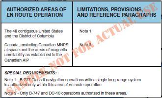
[Figure 3-32 Excerpt of Authorized Areas of En Route Operation]
Off-airway routes predicated on public navigation facilities and wholly contained within controlled airspace are published as direct Part 95 routes. Off-airway routes predicated on privately owned navigation facilities or not contained wholly within controlled airspace are published as off-airway non-Part 95 routes. In evaluating the adequacy of off-airway routes, the following items are considered; the type of aircraft and navigation systems used; proximity to military bases, training areas, low level military routes; and the adequacy of communications along the route. If you are a commercial operator, and you plan to fly off-airway routes, your OpsSpecs will likely address en route limitations and provisions regarding en route authorizations to use the global positioning system (GPS) or other RNAV systems in the NAS. Your POI must ensure that your long-range navigation program incorporates the required practices and procedures. These procedures must be in your manuals and in checklists, as appropriate. Training on the use of long range navigation equipment and procedures must be included in your training curriculums, and your minimum equipment lists (MELs) and maintenance programs must address the long range navigation equipment. Examples of other selected areas requiring specialized en route authorization include the following:
• Class I navigation in the U.S. Class A airspace using area or long range navigation systems.
• Class II navigation using multiple long range navigation systems.
• Operations in central East Pacific airspace.
• North Pacific operations.
• Operations within North Atlantic (NAT) minimum navigation performance specifications (MNPS) airspace.
• Operations in areas of magnetic unreliability.
• North Atlantic operation (NAT/OPS) with two engine airplanes under Part 121.
• Extended range operations (ER-OPS) with two engine airplanes under Part 121.
• Special fuel reserves in international operations.
• Planned inflight redispatch or rerelease en route.
• Extended over water operations using a single long-range communication system.
• Operations in reduced vertical separation minimum (RVSM) airspace.
DIRECT FLIGHTS
There are a number of ways to create shorter routes and fly off the airways. You can use NACO low and high altitude en route charts to create routes for direct flights, although many of the charts do not share the same scale as the adjacent chart, so a straight line is virtually impossible to use as a direct route for long distances. Generally speaking, NACO charts are plotted accurately enough to draw a direct route that can be flown. A straight line drawn on a NACO en route chart can be used to determine if a direct route will avoid airspace such as Class B airspace, restricted areas, prohibited areas, etc. Because NACO en route charts use the Lambert Conformal Conic projection, a straight line is as close as possible to a geodesic line (better than a great circle route). The closer that your route is to the two standard parallels of 33 degrees and 45 degrees on the chart, the better your straight line. There are cautions, however. Placing our round earth on a flat piece of paper causes distortions, particularly on long east-west routes. If your route is 180 degrees or 360 degrees, there is virtually no distortion in the course line.
About the only way you can confidently avoid protected airspace is by the use of some type of airborne database, including a graphic display of the airspace on the long-range navigation system moving map, for example. When not using an airborne database, leaving a few miles as a buffer helps ensure that you stay away from protected airspace.
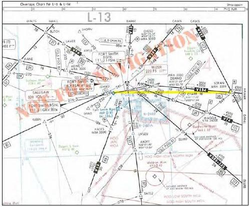
[Figure 3-33. Direct Route Navigation]
In Figure 3-33, a straight line on a magnetic course from SCRAN intersection of 270 degrees direct to the Fort Smith Regional Airport in Arkansas will pass just north of restricted area R-2401A and B, and R-2402. Since the airport and the restricted areas are precisely plotted, there is an assurance that you will stay north of the restricted areas. From a practical standpoint, it might be better to fly direct to the Wizer NDB. This route goes even further north of the restricted areas and places you over the final approach fix to Runway 25 at Fort Smith. One of the most common means for you to fly direct routes is to use conventional navigation such as VORs. When flying direct off-airway routes, remember to apply the FAA distance limitations, based upon NAVAID service volume.
RANDOM RNAV ROUTES
Random RNAV routes may be an integral solution in meeting the worldwide demand for increased air traffic system capacity and safety. Random RNAV routes are direct routes, based on RNAV capability. They are typically flown between waypoints defined in terms of latitude and longitude coordinates, degree and distance fixes, or offsets from established routes and airways at a specified distance and direction. Radar monitoring by ATC is required on all random RNAV routes.
With IFR certified RNAV units (GPS or FMS), there are several questions to be answered, including “Should I fly airways or should I fly RNAV direct?” One of the considerations is the determination of the MIA. In most places in the world at FL 180 and above, the MIA is not significant since you are well above any terrain or obstacles. On the other hand, a direct route at 18,000 feet from Salt Lake City, Utah to Denver, Colorado, means terrain and obstacles are very important. This RNAV direct route across the Rocky Mountains reduces your distance by about 17 NM, but radar coverage over the Rockies at lower altitudes is pretty spotty. This raises numerous questions. What will air traffic control allow on direct flights? What will they do if radar coverage is lost? What altitudes will they allow when they can’t see you on radar? Do they have altitudes for direct routes? The easy answer is to file the airways, and then all the airway MIAs become usable. But with RNAV equipment, a direct route is more efficient. Even though on some routes the mileage difference may be negligible, there are many other cases where the difference in distance is significant. ATC is required to provide radar separation on random RNAV routes at FL 450 and below. It is logical to assume that ATC will clear you at an altitude that allows it to maintain radar contact along the entire route, which could mean spending additional time and fuel climbing to an altitude that gives full radar coverage. All air route traffic control centers have MIAs for their areas of coverage. Although these altitudes are not published anywhere, they are available when airborne from ATC.
OFF ROUTE OBSTRUCTION CLEARANCE ALTITUDE
An off-route obstruction clearance altitude (OROCA) is an off-route altitude that provides obstruction clearance with a 1,000-foot buffer in nonmountainous terrain areas and a 2,000-foot buffer in designated mountainous areas within the U.S. This altitude may not provide signal coverage from ground-based navigational aids, air traffic control radar, or communications coverage. OROCAs are intended primarily as a pilot tool for emergencies and situational awareness. OROCAs depicted on NACO en route charts do not provide you with an acceptable altitude for terrain and obstruction clearance for the purposes of off-route, random RNAV direct flights in either controlled or uncontrolled airspace. OROCAs are not subject to the same scrutiny as MEAs, MVAs, MOCAs, and other minimum IFR altitudes. Since they do not undergo the same obstruction evaluation, Figure 3-33. Direct Route Navigation. 3-29 airport airspace analysis procedures, or flight inspection, they cannot provide the same level of confidence as the other minimum IFR altitudes.
If you depart an airport VFR intending to or needing to obtain an IFR clearance en route, you must be aware of the position of your aircraft relative to terrain and obstructions. When accepting a clearance below the MEA, MIA, MVA, or the OROCA, you are responsible for your own terrain/obstruction clearance until reaching the MEA, MIA, or MVA. If you are unable to visually maintain terrain/obstruction clearance, you should advise the controller and state your intentions.
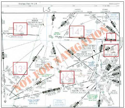
[Figure 3-34 Off-Route Obstacle Clearance Altitude]
For all random RNAV flights, there needs to be at least one waypoint in each ARTCC area through which you intend to fly. One of the biggest problems in creating an RNAV direct route is determining if the route goes through special use airspace. For most direct routes, the chances of going through prohibited, restricted, or special use airspace are good. In the U.S., all direct routes should be planned to avoid prohibited or restricted airspace by at least 3 NM. If a bend in a direct route is required to avoid special use airspace, the turning point needs to be part of the flight plan. Two of the most prominent long range navigation systems today include FMS with integrated GPS and stand-alone GPS. The following example is a simplified overview showing how the RNAV systems might be used to fly a random RNAV route:
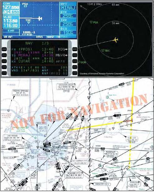
[Figure 3-35. Random RNAV Route]
In Figure 3-35 , you are northeast of Tuba City VORTAC at FL 200 using RNAV (showing both GPS and FMS), RNAV direct on a southwesterly heading to Lindbergh Regional Airport in Winslow. As you monitor your position and cross check your avionics against the high altitude en route chart, you receive a company message instructing you to divert to Las Vegas, requiring a change in your flight plan as highlighted on the depicted chart excerpt.
During your cockpit review of the high and low altitude en route charts, you determine that your best course of action is to fly direct to the MIRAJ waypoint, 28 DME northeast of the Las Vegas VORTAC on the 045° radial. This places you 193 NM out on a 259° magnetic course inbound, and may help you avoid diverting north, allowing you to bypass the more distant originating and intermediate fixes feeding into Las Vegas. You request an RNAV random route clearance direct MIRAJ to expedite your flight. Denver Center comes back with the following amended flight plan and initial clearance into Las Vegas:
“Marathon five sixty four, turn right heading two six zero, descend and maintain one six thousand, cleared present position direct MIRAJ.”
The latitude and longitude coordinates of your present position on the high altitude chart are N36 19.10, and W110 40.24 as you change your course. Notice your GPS moving map (upper left) and the FMS control display unit (below the GPS), and FMS map mode navigation displays (to the right of the GPS) as you reroute your flight to Las Vegas. For situational awareness, you note that your altitude is well above any of the OROCAs on your direct route as you arrive in the Las Vegas area using the low altitude chart.
PUBLISHED RNAV ROUTES
Although RNAV systems allow you to select any number of routes that may or may not be published on a chart, en route charts are still crucial and required for RNAV flight. They assist you with both flight planning and inflight navigation. NACO en route charts are very helpful in the context of your RNAV flights. Published RNAV routes are fixed, permanent routes that can be flight planned and flown by aircraft with RNAV capability. These are being expanded worldwide as new RNAV routes are developed, and existing charted, conventional routes are being designated for RNAV use. It is important to be alert to the rapidly changing application of RNAV techniques being applied to conventional en route airways. Published RNAV routes may potentially be found on any NACO en route chart. The published RNAV route designation may be obvious, or, on the other hand, RNAV route designations may be less obvious, as in the case where a published route shares a common flight track with a conventional airway. Note: Since the use of RNAV is dynamic and rapidly changing, NACO en route charts are continuously being updated for information changes and you may find some differences between charts.
According to the International Civil Aviation Organization (ICAO), who develops standard principles and techniques for international air navigation, basic designators for air traffic service (ATS) routes and their use in voice communications have been established in Annex 11. ATS is a generic ICAO term for flight information service, alerting service, air traffic advisory service, and air traffic control service. One of the main purposes of a system of route designators is to allow both pilots and ATC to make unambiguous reference to RNAV airways and routes. Many countries have adopted ICAO recommendations with regard to ATS route designations. Basic designators for ATS routes consist of a maximum of five, and in no case exceed six, alpha/numeric characters in order to be usable by both ground and airborne automation systems. The designator indicates the type of the route such as high/low altitude, specific airborne navigation equipment requirements such as RNAV, and the aircraft type using the route primarily and exclusively. The basic route designator consists of one or two letter(s) followed by a number from 1 to 999.
COMPOSITION OF DESIGNATORS
The prefix letters that pertain specifically to RNAV designations are included in the following list:
1. The basic designator consists of one letter of the alphabet followed by a number from 1 to 999. The letters may be:
a) A, B, G, R — for routes that form part of the regional networks of ATS routes and are not RNAV routes;
b) L, M, N, P — for RNAV routes that form part of the regional networks of ATS routes;
c) H, J, V, W — for routes that do not form part of the regional networks of ATS routes and are not RNAV routes;
d) Q, T, Y, Z — for RNAV routes that do not form part of the regional networks of ATS routes.
2. Where applicable, one supplementary letter must be added as a prefix to the basic designator as follows:
a) K — to indicate a low level route established for use primarily by helicopters.
b) U — to indicate that the route or portion thereof is established in the upper airspace;
c) S — to indicate a route established exclusively for use by supersonic airplanes during acceleration/deceleration and while in supersonic flight.
3. Where applicable, a supplementary letter may be added after the basic designator of the ATS route as a suffix as follows: a) F — to indicate that on the route or portion thereof advisory service only is provided;
b) G — to indicate that on the route or portion thereof flight information service only is provided;
c) Y — for RNP 1 routes at and above FL 200 to indicate that all turns on the route between 30° and 90° must be made within the tolerance of a tangential arc between the straight leg segments defined with a radius of 22.5 NM. 3-32
d) Z — for RNP 1 routes at and below FL 190 to indicate that all turns on the route between 30° and 90° shall be made within the tolerance of a tangential arc between the straight leg segments defined with a radius of 15 NM.
USE OF DESIGNATORS IN COMMUNICATIONS
In voice communications, the basic letter of a designator should be spoken in accordance with the ICAO spelling alphabet. Where the prefixes K, U or S, specified in 2., above, are used in voice communications, they should be pronounced as:
K = “Kopter” U = “Upper” S = “Supersonic” as in the English language.
Where suffixes “F”, “G”, “Y” or “Z” specified in 3., above, are used, the flight crew should not be required to use them in voice communications.
Example:
A11 will be spoken Alfa Eleven
UR5 will be spoken Upper Romeo Five
KB34 will be spoken Kopter Bravo Thirty Four
UW456 F will be spoken Upper Whiskey Four Fifty Six
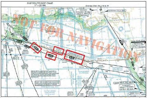
[Figure 3-36. Published RNAV Routes Replacing LF Airways]
Figure 3-36 depicts published RNAV routes in the Gulf of Mexico (black Q100, Q102, and Q105) that have been added to straighten out the flight segments and provide an alternative method of navigation to the LF airway (brown G26), that has since been terminated in this case. The “Q” designation is derived from the list of basic route designators previously covered, and correlates with the description for RNAV routes that do not form part of the regional networks of ATS routes. Notice the indirect reference to the RNAV requirement, with the note, “Navigational Equipment Other than LF or VHF Required.”
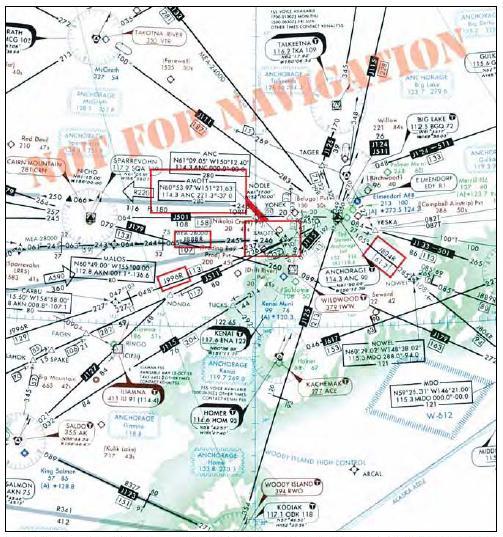
[Figure 3-37. Published RNAV Jet Routes]
Notice in Figure 3-37 that this en route chart excerpt depicts three published RNAV jet routes, J804R, J888R, and J996R. The “R” suffix is a supplementary route designator denoting an RNAV route. The overlapping symbols for the AMOTT intersection and waypoint indicate that AMOTT can be identified by conventional navigation or by latitude and longitude coordinates. Although coordinates were originally included for aircraft equipped with INS systems, they are now a good way to cross check between the coordinates on the chart and in the FMS or GPS databases to ensure you are tracking on your intended en route course. The AMOTT RNAV waypoint includes bearing and distance from the ANCHORAGE VORTAC. In an effort to simplify the conversion to RNAV, some controlling agencies outside the U.S. have simply designated all conventional routes as RNAV routes at a certain flight level.
RNAV MINIMUM EN ROUTE ALTITUDE
RNAV MEAs are depicted on some NACO IFR en route charts, allowing both RNAV and non-RNAV pilots to use the same chart for instrument navigation.
MINIMUM IFR ALTITUDE
The Minimum IFR altitude (MIA) for operations is prescribed in Part 91. These MIAs are published on NACO charts and prescribed in Part 95 for airways and routes, and in Part 97 for standard instrument approach procedures. If no applicable minimum altitude is prescribed in Parts 95 or 97, the following MIA applies: In designated mountainous areas, 2,000 feet above the highest obstacle within a horizontal distance of 4 NM from the course to be flown; or other than mountainous areas, 1,000 feet above the highest obstacle within a horizontal distance of 4 NM from the course to be flown; or as otherwise authorized by the Administrator or assigned by ATC. MIAs are not flight checked for communication.
WAYPOINTS
Waypoints are specified geographical locations, or fixes, used to define an RNAV route or the flight path of an aircraft employing RNAV. Waypoints may be any of the following types: predefined, published waypoints, floating waypoints, or user-defined waypoints. Predefined, published waypoints are defined relative to VOR-DME or VORTAC stations or, as with GPS, in terms of latitude/longitude coordinates.
USER-DEFINED WAYPOINTS
Pilots typically create user-defined waypoints for use in their own random RNAV direct navigation. They are newly established, unpublished airspace fixes that are designated geographic locations/positions that help provide positive course guidance for navigation and a means of checking progress on a flight. They may or may not be actually plotted by the pilot on en route charts, but would normally be communicated to ATC in terms of bearing and distance or latitude/longitude. An example of user-defined waypoints typically includes those derived from database RNAV systems whereby latitude/longitude coordinate-based waypoints are generated by various means including keyboard input, and even electronic map mode functions used to establish waypoints with a cursor on the display. Another example is an offset phantom waypoint, which is a point-in-space formed by a bearing and distance from NAVAIDs, such as VORTACs and tactical air navigation (TACAN) stations, using a variety of navigation systems. When specifying unpublished waypoints in a flight plan, they can be communicated using the frequency/bearing/distance format or latitude and longitude, and they automatically become compulsory reporting points unless otherwise advised by ATC. All airplanes with latitude and longitude navigation systems flying above FL 390 must use latitude and longitude to define turning points.
FLOATING WAYPOINTS
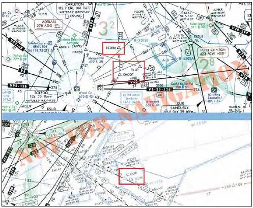
[Figure 3-38. Floating Waypoints]
Floating waypoints, or reporting points, represent airspace fixes at a point in space not directly associated with a conventional airway. In many cases, they may be established for such purposes as ATC metering fixes, holding points, RNAV-direct routing, gateway waypoints, STAR origination points leaving the en route structure, and SID terminating points joining the en route structure.
In Figure 3-38, in the top example, a NACO low altitude en route chart depicts three floating waypoints that have been highlighted, SCORR, FILUP, and CHOOT. Notice that waypoints are named with five-letter identifiers that are unique and pronouncable. Pilots must be careful of similar waypoint names. Notice on the high altitude en route chart excerpt in the bottom example, the similar sounding and spelled floating waypoint named SCOOR, rather than SCORR. This emphasizes the importance of correctly entering waypoints into database-driven navigation systems. One waypoint character incorrectly entered into your navigation system could adversely affect your flight. The SCOOR floating reporting point also is depicted on a Severe Weather Avoidance Plan (SWAP) en route chart. These waypoints and SWAP routes assist pilots and controllers when severe weather affects the East Coast.
COMPUTER NAVIGATION FIXES
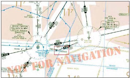
[Figure 3-39. Computer Navigation Fix]
An integral part of RNAV using en route charts typically involves the use of airborne navigation databases. Database identifiers are depicted on NACO en route charts enclosed in parentheses, for example AWIZO waypoint, shown in Figure 3-39. These identifiers, sometimes referred to as computer navigation fixes (CNFs), have no ATC function and should not be used in filing flight plans nor should they be used when communicating with ATC. Database identifiers on en route charts are shown only to enable you to maintain orientation as you use charts in conjunction with database navigation systems, including RNAV.
Many of the RNAV systems available today make it all too easy to forget that en route charts are still required and necessary for flight. As important as databases are, they really are onboard the airplane to provide navigation guidance and situational awareness; they are not intended as a substitute for paper charts. When flying with GPS, FMS, or planning a flight with a computer, it is important to understand the limitations of the system you are using, for example, incomplete information, uncodeable procedures, complex procedures, and database storage limitations. For more information on databases, refer to Appendix A, Airborne Navigation Database.
HIGH ALTITUDE AIRSPACE REDESIGN
Historically in the U.S., IFR flights have navigated along a system of Federal Airways that require pilots to fly directly toward or away from ground-based navigation aids. RNAV gives users the capability to fly direct routes between any two points, offering far more flexible and efficient en route operations in the high-altitude airspace environment. As part of the ongoing National Airspace Redesign (NAR), the FAA has implemented the High Altitude Redesign (HAR) program with the goal of obtaining maximum system efficiency by introducing advanced RNAV routes for suitably equipped aircraft to use.
Q-ROUTES
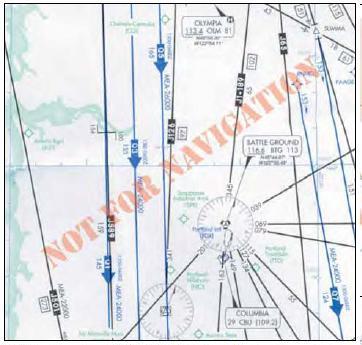
[Figure 3-40. Q-Route]
Naturally, the routes between some points are very popular, so these paths are given route designators and published on charts. The U.S. and Canada use "Q" as a designator for RNAV routes. Q-Routes 1 through 499 are allocated to the U.S., while Canada is allocated Q-Routes numbered from 500 through 999. The first Q-Routes were published in 2003. One benefit of this system is that aircraft with RNAV or RNP capability can fly safely along closely spaced parallel flight paths on high-density routes, which eases airspace congestion. While the initial overall HAR implementation will be at FL390 and above, some of the features may be used at lower altitudes, and some Q-Routes may be used as low as FL180. A Q-Route is shown in figure 3-40.
NON-RESTRICTIVE ROUTING
HAR also includes provisions for pilots to choose their own routes, unconstrained by either conventional airways or Q-Routes. This non-restrictive routing (NRR) allows pilots of RNAV-equipped aircraft to plan the most advantageous route for the flight. There are two ways to designate an NRR route on your flight plan. One method, point-to-point (PTP), uses the traditional fixes in the aircraft equipment database and is shown by placing “PTP” in the first part of the “Remarks” block of the flight plan. For aircraft that have the additional waypoints of the Navigation Reference System (NRS) in their databases, “HAR” is placed in the first part of the “Remarks” block.
NAVIGATION REFERENCE SYSTEM
The NRS is a grid of waypoints overlying the U.S. that will be the basis for flight plan filing and operations in the redesigned high altitude environment. It will provide increased flexibility to aircraft operators and controllers. The NRS supports flight planning in a NRR environment and provides ATC with the ability to more efficiently manage tactical route changes for aircraft separation, traffic flow management, and weather avoidance. It provides navigation reference waypoints that pilots can use in requesting route deviations around weather areas, which will improve common understanding between pilots and ATC of the desired flight path. The NRS will initially include waypoints every 30 minutes of latitude and every two degrees of longitude. In its final version, the NRS waypoints will have a grid resolution of 1-degree longitude by 10 minutes of latitude. As database capabilities for the preponderance of aircraft operating in the high altitude airspace environment becomes adequate to support more dense NRS resolution, additional NRS waypoints will be established.
T-ROUTES
T-Routes are being created for those who operate at lower altitudes. T-Routes have characteristics that are similar to Q-Routes, but they are depicted on low altitude en route charts and are intended for flights below FL180. The first T-Routes are being pioneered in Alaska.
IFR TRANSITION ROUTES
In order to expedite the handling of IFR overflight traffic through Charlotte Approach Control Airspace, several RNAV routes are published in the Airport/Facility Directory and available for you when filing your flight plan. Any RNAV capable aircraft filing flight plan equipment codes of /E, /F, or /G may file for these routes. Other aircraft may request vectors along these routes but should only expect vector routes Figure 3-40. Q-Route 3-37 as workload permits. Altitudes are assigned by ATC based upon traffic.
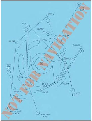
[Figure 3-41 IFR Transition Routes in the Airport/Facility Directory.]
IFR transition routes through Class B airspace for general aviation aircraft en route to distant destinations are highly desirable. Since general aviation aircraft cruise at altitudes below the ceiling of most Class B airspace areas, access to that airspace for en route transition reduces cost and time, and is helpful to pilots in their flight planning. Establishing RNAV fixes could facilitate the implementation of IFR transition routes, although every effort should be made to design routes that can be flown with RNAV or VOR equipment. IFR transition routes are beneficial even if access is not available at certain times because of arriving or departing traffic saturation at the primary airport. For these locations, information can be published to advise pilots when IFR transition access is not available.
REQUIRED NAVIGATION PERFORMANCE
As RNAV systems grow in sophistication, high technology FMS and GPS avionics are gaining popularity as NDBs, VORs, and LORAN are being phased out. As a result, new procedures are being introduced, including RNP, RVSM, and minimum navigation performance specifications (MNPS). ICAO defines an RNP “X” specification as requiring on-board performance monitoring and alerting. Even such terms as gross navigation errors (GNEs) are being introduced into the navigation equation. If you commit a GNE in the North Atlantic oceanic region of more than 25 NM laterally or 300 feet vertically, it has a detrimental effect on the overall targeted level of safety of the ATC airspace system in this region. This applies to commercial operators, as well as Part 91 operators, all of whom must be knowledgeable on procedures for operations in North Atlantic airspace, contained in the North Atlantic MNPS Operations Manual.
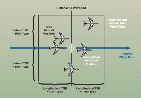
[Figure 3-42. ICAO RNP Containment Parameters]
RNP types are identified by a single accuracy value. For example, RNP 1 refers to a required navigation performance accuracy within 1 NM of the desired flight path at least 95 percent of the flying time. Countries around the world are establishing required navigation performance values. For Federal Airways in the U.S. that extend 4 NM from either side of the airway centerline, the airway has an equivalent RNP of 2. Figure 3-42 shows ICAO RNP containment parameters, including reference to lateral and longitudinal total system errors (TSEs).
RNP requires you to learn new procedures, communications, and limitations; and to learn new terminology that defines and describes navigation concepts. One of these terms is RNP Airspace, a generic term designating airspace, routes, legs, operations, or procedures where minimum RNP has been established. P-RNAV represents a 95 percent containment value of ±1 NM. B-RNAV provides a 95 percent containment value of ±5 NM. RNP is a function of RNAV equipment that calculates, displays, and provides lateral guidance to a profile or path. Estimated position error (EPE) is a measure of your current estimated navigational performance, also referred to as actual navigation performance (ANP).
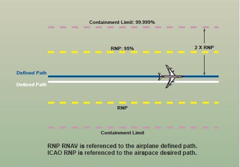
[Figure 3-43. RNP RNAV Containment.]
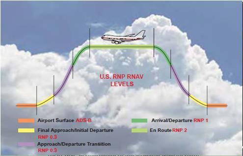 ]
]
[Figure 3-44. Airspace Control Regions]
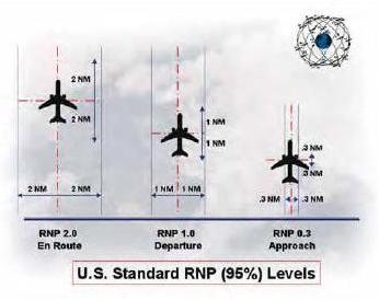
[Figure 3-45. U.S. Standard RNP Levels]
RNP RNAV is an industry-expanded specification beyond ICAO-defined RNP. Some of the benefits of RNP RNAV includes being an aid in both separation and collision risk assessment. RNP RNAV can further reduce route separation. Figure 3-43 depicts route separation, that can now be reduced to four times the RNP value, which further increases route capacity within the same airspace. The containment limit quantifies the navigation performance where the probability of an unannunciated deviation greater than 2 x RNP is less than 1 x 10⁻⁵. This means that the pilot will be alerted when the TSE can be greater than the containment limit. Figure 3-44 shows the U.S. RNP RNAV levels by airspace control regions, including RNP 2 for the en route phase of flight, and Figure 3-45 illustrates the U.S. standard RNP (95%) levels.
REDUCED VERTICAL SEPARATION MINIMUMS
In 1960, the minimum vertical separation between airplanes above FL 290 was officially increased to 2,000 feet. This was necessary because of the relatively large errors in barometric altimeters at high altitudes. Since that time, increased air traffic worldwide has begun to approach (and sometimes exceed) the capacity of the most popular high-altitude routes. Likewise, very accurate altitude determination by satellite positioning systems makes it possible to change the minimum vertical separation for properly equipped airplanes back to the pre-1960 standard of 1,000 feet.
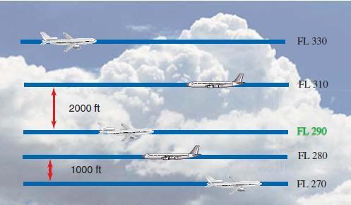
[Figure 3-46. Prior to implementation of RVSM, all traffic above FL290 required vertical separation of 2,000 feet]
RVSM airspace is any airspace between FL 290 and FL 410 inclusive,where airplanes are separated by 1,000 feet vertically. In the early 1980’s, programs were established to study the concept of reduced vertical separation minimums (RVSM). RVSM was found to be technically feasible without imposing unreasonable requirements on equipment. RVSM is the most effective way to increase airspace capacity to cope with traffic growth. Most of the preferred international and domestic flight routes are under both RVSM and RNP RNAV rules.
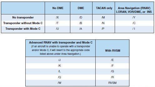
[Figure 3-47. When filed in your IFR flight plan, these codes inform ATC about your aircraft navigation capability]
In 1997, the first RVSM 1,000-foot separation was implemented between FL 330 and FL 370 over the North Atlantic. In 1998, RVSM was expanded to include altitudes from FL 310 to FL 390. Today States (governments) around the globe are implementing RVSM from FL 290 to FL 410. There are many requirements for operator approval of RVSM. Each aircraft must be in compliance with specific RVSM criteria. A program must be in place to assure continued airworthiness of all RVSM critical systems. Flight crews, dispatchers, and flight operations must be properly trained, and operational procedures, checklists, etc. must be established and published in the Ops Manual and AFM, plus operators must participate in a height monitoring program.
Using the appropriate suffix in Block 3 on the IFR flight plan lets ATC know that your flight conforms to the necessary standards and is capable of using RNP routes or flying in RVSM airspace. The equipment codes changed significantly in 2005 and are shown in Figure 3-47. Figure 3-45. U.S. Standard RNP Levels. 3-41 FL 330 FL 310 FL 290 FL 280 FL 270 2000 ft 1000 ft Figure 3-46. Prior to implementation of RVSM, all traffic above FL290 required vertical separation of 2,000 feet. Figure 3-47. When filed in your IFR flight plan, these codes inform ATC about your aircraft navigation capability.
Selected Knowledge field from the left to find out more about knowledge related to Pilot Training.
Click here to get a complete list of Aircraft Schools the entire United States.
Copyright © 2012 AirplaneGroundSchools.com | All Rights Reserved
Design G. Wolfgang | W3C XHTML 1.0 | W3C CSS 2.0
Courtesy Open Web Design![]() Thanks to Florida Vacation Homes
Thanks to Florida Vacation Homes