Airplane Ground Schools
Knowledge of Flying is Our passion.
Serving the General Aviation Community
This chapter presents information on instrument flight rule (IFR) helicopter operations in the National Airspace System (NAS). Although helicopter instrument flight is relatively new when compared to airplane instrument flight, the global positioning system (GPS) and the developing Wide Area Augmentation System (WAAS) are bringing approach procedures to heliports around the country. As of February 2006 there were approximately 45 public “Copter” instrument flight procedures, including 23 instrument landing system (ILS), 5 RNAV (GPS) point-in-space (PinS), 6 non-directional beacon (NDB), 8 VHF Omni-directional Range (VOR), and 227 private RNAV (GPS) “Specials” either to runways or PinS approaches to heliports. This does not include approach procedures that are located five miles or more from shore in the Gulf of Mexico and other locations.
The ability to operate helicopters under IFR increases their utility and safety. Helicopter IFR operators have an excellent safety record due to the investment in IFR equipped helicopters, development of instrument approach procedures, and IFR trained flight crews. The safety record of IFR operations in the Gulf of Mexico is equivalent to the safety record of the best-rated airlines. Manufacturers are working to increase IFR all-weather capabilities of helicopters by providing slower minimum instrument airspeeds (VMINI), faster cruising speeds, and better autopilots and flight management systems (FMS). As a result, in October 2005, the first civil helicopter in the United States was certified for flight into known icing conditions.
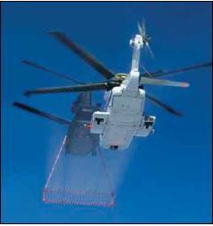
[Figure 7-1 Icing Tests]
HELICOPTER IFR CERTIFICATION
It is very important that pilots be familiar with the IFR requirements for their particular helicopter. Within the same make, model and series of helicopter, variations in the installed avionics may change the required equipment or the level of augmentation for a particular operation. The Automatic Flight Control System/Autopilot/Flight Director (AFCS/AP/FD) equipment installed in IFR helicopters can be very complex. For some helicopters, the AFCS/AP/FD complexity will require formal training in order for the pilot(s) to obtain and maintain a high level of knowledge of system operation, limitations, failure indications and reversionary modes. For a helicopter to be certified to conduct operations in instrument meteorological conditions (IMC), it must meet the design and installation requirements of Title 14 Code of Federal Regulations (14 CFR) Part 27, Appendix B (Normal Category) and Part 29, Appendix B (Transport Category), which are in addition to the visual flight rule (VFR) requirements.
These requirements are broken down into the following categories: flight and navigation equipment, miscellaneous requirements, stability, helicopter flight manual limitations, operations specifications, and minimum equipment list (MEL).
FLIGHT AND NAVIGATION EQUIPMENT
The basic installed flight and navigation equipment for helicopter IFR operations is listed under Part 29.1303, with amendments and additions in Appendix B of Parts 27 and 29 under which they are certified. The list includes:
• Clock.
• Airspeed indicator.
• Sensitive altimeter adjustable for barometric pressure1.
• Magnetic direction indicator.
• Free-air temperature indicator.
• Rate-of-climb (vertical speed) indicator.
• Magnetic gyroscopic direction indicator.
• Standby bank and pitch (attitude) indicator.
• Non-tumbling gyroscopic bank and pitch (attitude) indicator.
• Speed warning device (if required by Part 29).
MISCELLANEOUS REQUIREMENTS
• Overvoltage disconnect.
• Instrument power source indicator.
• Adequate ice protection of IFR systems.
• Alternate static source (single pilot configuration). • Thunderstorm lights (transport category helicopters).
STABILIZATION AND AUTOMATIC FLIGHT CONTROL SYSTEM (AFCS)
Helicopter manufacturers normally use a combination of a stabilization and/or AFCS in order to meet the IFR stability requirements of Parts 27 and 29. These systems include:
• Aerodynamic surfaces, which impart some stability or control capability that generally is not found in the basic VFR configuration.
• Trim systems, which provide a cyclic centering effect. These systems typically involve a magnetic brake/spring device, and may be controlled by a four-way switch on the cyclic. This system supports “hands on” flying of the helicopter.
• Stability Augmentation Systems (SASs), which provide short-term rate damping control inputs to increase helicopter stability. Like trim systems, SAS supports “hands on” flying.
• Attitude Retention Systems (ATTs), which return the helicopter to a selected attitude after a disturbance. Changes in attitude can be accomplished usually through a four-way “beep” switch, or by actuating a “force trim” switch on the cyclic, which sets the desired attitude manually. Attitude retention may be a SAS function, or may be the basic “hands off” autopilot function.
• Autopilot Systems (APs) provide for “hands off” flight along specified lateral and vertical paths. The functional modes may include heading, altitude, vertical speed, navigation tracking, and approach. APs typically have a control panel for mode selection and indication of mode status. APs may or may not be installed with an associated flight director (FD). APs typically control the helicopter about the roll and pitch axes (cyclic control) but may also include yaw axis (pedal control) and collective control servos.
• Flight Directors (FDs), which provide visual guidance to the pilot to fly selected lateral and vertical modes of operation. The visual guidance is typically provided by a “single cue,” commonly known as a “vee bar,” which provides the indicated attitude to fly and is superimposed on the attitude indicator. Other flight directors may use a “two cue” presentation known as a “cross pointer system.” These two presentations only provide attitude information. A third system, known as a “three cue” system, provides information to position the collective as well as attitude (roll and pitch) cues. The collective control cue system identifies and cues the pilot which collective control inputs to use when path errors are produced, or when airspeed errors exceed preset values. The three-cue system pitch command provides the required cues to control airspeed when flying an approach with vertical guidance at speeds slower than the best-rate-of-climb (BROC) speed. The pilot manipulates the helicopter’s controls to satisfy these commands, yielding the desired flight path, or may couple the autopilot to the flight director to fly along the desired flight path. Typically, flight director mode control and indication are shared with the autopilot.
Pilots must be aware of the mode of operation of the augmentation systems, and the control logic and functions in use. For example, on an ILS approach and using the three-cue mode (lateral, vertical and collective cues), the flight director collective cue responds to glideslope deviation, while the horizontal bar cue of the "cross-pointer" responds to airspeed deviations. However, the same system when operated in the twocue mode on an ILS, the flight director horizontal bar cue responds to glideslope deviations. The need to be aware of the flight director mode of operation is particularly significant when operating using two pilots. Pilots should have an established set of procedures and responsibilities for the control of flight director/autopilot modes for the various phases of flight. Not only does a full understanding of the system modes provide for a higher degree of accuracy in control of the helicopter, it is the basis for crew identification of a faulty system.
HELICOPTER FLIGHT MANUAL LIMITATIONS
Helicopters are certificated for IFR operations with either one or two pilots. Certain equipment is required to be installed and functional for two-pilot operations and additional equipment is required for single pilot operation.
In addition, the Helicopter Flight Manual defines systems and functions that are required to be in operation or engaged for IFR flight in either the single or twopilot configurations. Often, in a two-pilot operation, this level of augmentation is less than the full capability of the installed systems. Likewise, a single-pilot operation may require a higher level of augmentation.
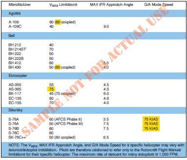
[Figure 7-2 VMINI Limitations, Maximum IFR Approach Angles and G/A Mode Speeds for selected IFR-certified helicopters]
The Helicopter Flight Manual also identifies other specific limitations associated with IFR flight. Typically, these limitations include, but are not limited to:
• Minimum equipment required for IFR flight (in some cases, for both single-pilot and two-pilot operations).
• VMINI (minimum speed - IFR).
• VNEI (never exceed speed - IFR).
• Maximum approach angle.
• Weight and center of gravity limits.
• Helicopter configuration limitations (such as door positions and external loads).
• Helicopter system limitations (generators, inverters, etc.).
• System testing requirements (many avionics and AFCS,AP, and FD systems incorporate a self-test feature).
• Pilot action requirements (for example, the pilot must have hands and feet on the controls during certain operations, such as an instrument approach below certain altitudes).
Final approach angles/descent gradient for public approach procedures can be as high as 7.5 degrees/795 feet per NM. At 70 KIAS (no wind) this equates to a descent rate of 925 FPM. With a 10-knot tailwind the descent rate increases to 1,056 FPM. “Copter” PinS approach procedures are restricted to helicopters with a maximum VMINI of 70 KIAS and an IFR approach angle that will enable them to meet the final approach angle/descent gradient. Pilots of helicopters with a VMINI of 70 KIAS may have inadequate control margins to fly an approach that is designed with the maximum allowable angle/descent gradient or minimum allowable deceleration distance from the MAP to the heliport. The “Copter” PinS final approach segment is limited to 70 KIAS since turn containment and the deceleration distance from the MAP to the heliport may not be adequate at faster speeds. For some helicopters, (highlighted yellow in Figure 7-2) engaging the autopilot may increase the VMINI to a speed greater than 70 KIAS, or in the “goaround” mode require a speed faster than 70 KIAS. It may be possible for these helicopters to be flown manually on the approach, or on the missed approach in a mode other than the G/A mode.
Since slower IFR approach speeds enable the helicopter to fly steeper approaches and reduces the distance from the heliport that is required to decelerate the helicopter, you may want to operate your helicopter at speeds slower than its established VMINI. The provision to apply for a determination of equivalent safety for instrument flight below VMINI and the minimum helicopter requirements are specified in Advisory Circulars (AC) 27-1, Certification of Normal Category Rotorcraft and AC 29-2C, Certification of Transport Category Rotorcraft. Application guidance is available from the Rotorcraft Directorate Standards Staff, ASW-110, 2601 Meacham Blvd. Fort Worth, Texas 76137-4298, (817) 222-5111.
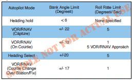
[Figure 7-3. Autopilot Bank Angle and Roll Rate Limits for the S-76 used by the William J. Hughes Technical Center for Flight Tests.]
Performance data may not be available in the Helicopter Flight Manual for speeds other than the best rate of climb speed. To meet missed approach climb gradients pilots may use observed performance for similar weight, altitude, temperature, and speed conditions to determine equivalent performance. When missed approaches utilizing a climbing turn are flown with an autopilot, set the heading bug on the missed approach heading, and then at the MAP, engage the indicated airspeed mode, followed immediately by applying climb power and selecting the heading mode. This is important since the autopilot roll rate and maximum bank angle in the Heading Select mode are significantly more robust than in the NAV mode. Figure 7-3 represents the bank angle and roll limits of the S- 76 used by the FAA for flight testing. It has a roll rate in the Heading Select mode of 5 degrees per second with only 1 degree per second in the NAV mode. The bank angle in the Heading Select mode is 20 degrees with only 17 degrees in the NAV Change Over mode. Furthermore, if the Airspeed Hold mode is not selected on some autopilots when commencing the missed approach, the helicopter will accelerate in level flight until the best rate of climb is attained, and only then will a climb begin.
Wide area augmentation system (WAAS) localizer performance (LP) lateral-only PinS testing conducted in 2005 by the FAA at the William J. Hughes Technical Center in New Jersey for helicopter PinS also captured the flight tracks for turning missed approaches.
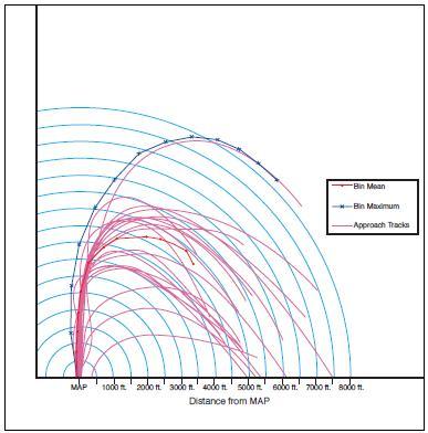
[Figure 7-4 Flight tests at the William J. Hughes Technical Center point out the importance of airspeed control and using the
correct technique to make a turning missed approach]
The large flight tracks that resulted during the turning missed approach were attributed in part to operating the autopilot in the NAV mode and exceeding the 70 KIAS limit.
OPERATIONS SPECIFICATIONS
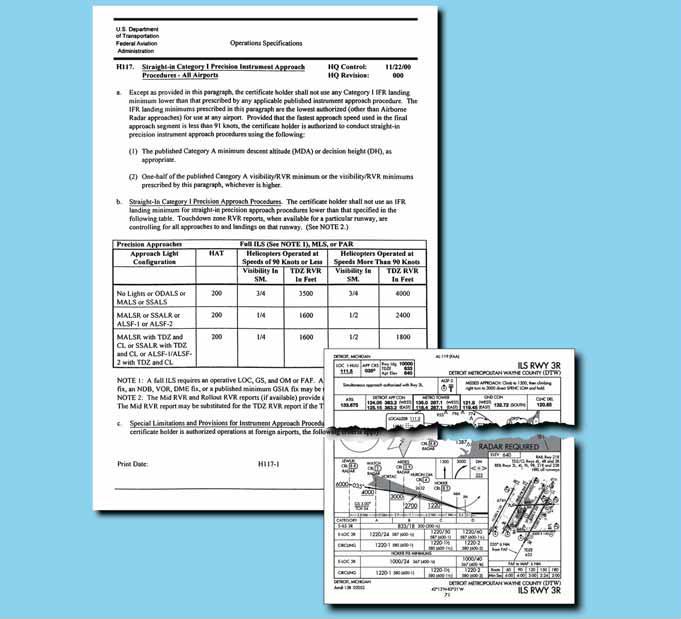
[Figure 7-5. Operations Specifications]
A flight operated under Part 135 has minimums and procedures more restrictive than a flight operated under Part 91. These Part 135 requirements are detailed in their operations specifications (OpsSpecs). Helicopter Emergency Medical Service (HEMS) operators have even more restrictive OpsSpecs. Figure 7-5 is an excerpt from an OpsSpecs detailing the minimums for precision approaches. The inlay in Figure 7-5 shows the minimums for the ILS Rwy 3R approach at Detroit Metro Airport. With all lighting operative, the minimums for helicopter Part 91 operations are a 200-foot ceiling, and 1200-feet runway visual range (RVR) (one-half airplane Category A visibility but no less than 1/4 SM/1200 RVR). However, as shown in the OpsSpecs, the minimum visibility this Part 135 operator must adhere to is 1600 RVR. Pilots operating under Part 91 are encouraged to develop their own personal OpsSpecs based on their own equipment, training, and experience.
MINIMUM EQUIPMENT
LIST A helicopter operating under Part 135 with certain installed equipment inoperative is prohibited from taking off unless the operation is authorized in the approved MEL. The MEL provides for some equipment to be inoperative if certain conditions are met
.JPG)
[Figure 7-6. Example of a Minimum Equipment List (MEL) ].
In many cases, a helicopter configured for single-pilot IFR may depart IFR with certain equipment inoperative, provided a crew of two pilots is used. Under Part 91, a pilot may defer certain items without an MEL if those items are not required by the type certificate, CFRs, or airworthiness directives (ADs), and the flight can be performed safely without them. If the item is disabled, or removed, or marked inoperative, a logbook entry is made.
PILOT PROFICIENCY
Helicopters of the same make and model may have variations in installed avionics that change the required equipment or the level of augmentation for a particular operation. The complexity of modern AFCS, AP, and FD systems requires a high degree of understanding to safely and efficiently control the helicopter in IFR operations. Formal training in the use of these systems is highly recommended for all pilots. Bin Mean Bin Maximum Approach Tracks MAP 1000 ft. 2000 ft. 3000 ft. 4000 ft. 5000 ft. 6000 ft. 7000 ft. 8000 ft. Distance from MAP Figure 7-4. Flight tests at the William J. Hughes Technical Center point out the importance of airspeed control and using the correct technique to make a turning missed approach. During flight operations, you must be aware of the mode of operation of the augmentation system, and the control logic and functions employed. For example, during an ILS approach using a particular system in the three-cue mode (lateral, vertical, and collective cues), the flight director collective cue responds to glide slope deviation, while the horizontal bar of the “cross-pointer” responds to airspeed deviations. The same system, while flying an ILS in the two-cue mode, provides for the horizontal bar to respond to glide slope deviations. This concern is particularly significant when the crew consists of two pilots. Pilots should establish a set of procedures and division of responsibility for the control of flight director/autopilot and FMS modes for the various phases of flight. Not only is a full understanding of the system modes essential in order to provide for a high degree of accuracy in control of the helicopter, it is the basis for identification of system failures.
HELICOPTER VFR MINIMUMS
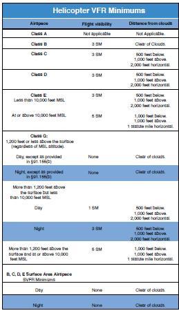
[Figure 7-7. Helicopter VFR Minimums. ]
Helicopters have the same VFR minimums as airplanes with two exceptions. In Class G airspace or under a special visual flight rule (SVFR) clearance, helicopters have no minimum visibility requirement but must remain clear of clouds and operate at a speed that is slow enough to give the pilot an adequate opportunity to see other aircraft or an obstruction in time to avoid a collision. Helicopters are also authorized (Part 91, appendix D, section 3) to obtain SVFR clearances at airports with the designation NO SVFR in the Airport Facility Directory (A/FD) or on the sectional chart. Figure 7-7 shows the visibility and cloud clearance requirements for VFR and SVFR. However, lower minimums associated with Class G airspace and SVFR do not take the place of the VFR minimum requirements of either Part 135 regulations or respective OpsSpecs.
Knowledge of all VFR minimums is required in order to determine if a Point-in-Space (PinS) approach can be conducted, or if a SVFR clearance is required to continue past the missed approach point (MAP). These approaches and procedures will be discussed in detail later.
HELICOPTER IFR TAKEOFF MINIMUMS
A pilot operating under Part 91 has no takeoff minimums with which to comply other than the requirement to attain VMINI before entering instrument meteorological conditions (IMC). For most helicopters, this requires a distance of approximately 1/2 mile and an altitude of 100 feet. If departing with a steeper climb gradient, some helicopters may require additional altitude to accelerate to VMINI. To maximize safety, always consider using the Part 135 operator standard takeoff visibility minimum of 1/2 statute mile (SM) or the charted departure minima, whichever is higher. A charted departure that provides protection from obstacles will either have a higher visibility requirement, climb gradient, and/or departure path. Part 135 operators are required to adhere to the takeoff minimums prescribed in the instrument approach procedures (IAPs) for the airport.
HELICOPTER IFR ALTERNATES
The pilot must file for an alternate if weather reports and forecasts at the proposed destination do not meet certain minimums. These minimums differ for Part 91 and Part 135 operators. PART 91 OPERATORS Part 91 operators are not required to file an alternate if, at the estimated time of arrival (ETA) and for 1 hour after, the ceiling will be at least 1,000 feet above the airport elevation or 400 feet above the lowest applicable approach minima, whichever is higher, and the visibility is at least 2 SM. If an alternate is required, an airport can be used if the ceiling is at least 200 feet above the minimum for the approach to be flown and visibility is at least 1 SM, but never less than the minimum required for the approach to be flown. If no instrument approach procedure has been published for the alternate airport, the ceiling and visibility minima are those allowing descent from the MEA, approach, and landing under basic VFR.
PART 135 OPERATORS
Part 135 operators are not required to file an alternate if, for at least 1 hour before and 1 hour after the ETA, the ceiling will be at least 1,500 feet above the lowest circling approach minimum descent altitude (MDA). If a circling instrument approach is not authorized for the airport, the ceiling must be at least 1,500 feet above the lowest published minimum or 2,000 feet above the airport elevation, whichever is higher. For the instrument approach procedure to be used at the destination airport, the forecasted visibility for that airport must be at least 3 SM, or 2 SM more than the lowest applicable visibility minimums, whichever is greater.
Alternate landing minimums for flights conducted under Part 135 are described in the OpsSpecs for that operation. All helicopters operated under IFR must carry enough fuel to fly to the intended destination, fly from that airport to the filed alternate, if required, and continue for 30 minutes at normal cruising speed.
HELICOPTER INSTRUMENT APPROACHES
Helicopter instrument flight is relatively new when compared to airplane instrument flight. Many new helicopter instrument approach procedures have been developed to take advantage of advances in both avionics and helicopter technology.
STANDARD INSTRUMENT APPROACH PROCEDURES TO AN AIRPORT
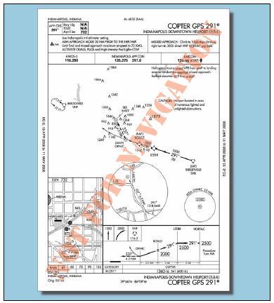
Helicopters flying standard instrument approach procedures (SIAP) must adhere to the MDA or decision altitude for Category A airplanes, and may apply the Part 97.3(d-1) rule to reduce the airplane Category A visibility by half but in no case less than 1/4 SM or 1200 RVR.
The approach can be initiated at any speed up to the highest approach category authorized; however, the speed on the final approach segment must be reduced to the Category A speed of less than 90 KIAS before the MAP in order to apply the visibility reduction. A constant airspeed is recommended on the final approach segment to comply with the stabilized approach concept since a decelerating approach may make early detection of wind shear on the approach path more difficult.
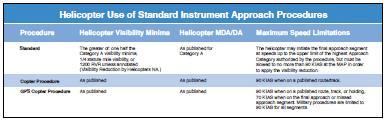
[Figure 7-8 Helicopter Use of Standard Instrument Approach Procedures]
When visibility minimums must be increased for inoperative components or visual aids, use the Inoperative Components and Visual Aids Table (provided in the front cover of the U.S. Terminal Procedures) to derive the Category A minima before applying any visibility reduction. The published visibility may be increased above the standard visibility minima due to penetrations of the 20:1 and 34:1 final approach obstacle identification surfaces (OIS). The minimum visibility required for 34:1 penetrations is 3/4 SM and for 20:1 penetrations 1 SM (see Chapter 5). When there are penetrations of the final approach OIS, a visibility credit for approach lighting systems is not allowed for either airplane or helicopter procedures that would result in values less than the appropriate 3/4 SM or 1 SM visibility requirement. The Part 97.3 visibility reduction rule does not apply, and you must take precautions to avoid any obstacles in the visual segment. Procedures with penetrations of the final approach OIS will be annotated at the next amendment with “Visibility Reduction by Helicopters NA.”
Until all the affected SIAPs have been annotated, an understanding of how the standard visibilities are established is the best aid in determining if penetrations of the final approach OIS exists. Some of the variables in determining visibilities are: DA/MDA height above touchdown (HAT), height above airport (HAA), distance of the facility to the MAP (or the runway threshold for non-precision approaches), and approach lighting configurations.
The standard visibility requirement, without any credit for lights, is 1 SM for nonprecision approaches and 3/4 SM for precision approaches. This is based on a Category A airplane 250-320 feet HAT/HAA, and for nonprecision approaches a distance of 10,000 feet or less from the facility to the MAP (or runway threshold). For precision approaches, credit for any approach light configuration, and for non-precision approaches (with a 250 HAT) configured with a MALSR, SSALR, or ALSF-1 normally results in a published visibility of 1/2 SM.
Consequently, if an ILS is configured with approach lights or a nonprecision approach is configured with either MALSR, SSALR, or ALSF-1 lighting configurations and the procedure has a published visibility of 3/4 SM or greater, a penetration of the final approach OIS may exist. Also, pilots will be unable to determine whether there are penetrations of the final approach OIS if a nonprecision procedure does not have approach lights, or is configured with ODALS, MALS, or SSALS/SALS lighting since the minimum published visibility will be 3/4 SM or greater.
As a rule of thumb, approaches with published visibilities of 3/4 SM or more should be regarded as having final approach OIS penetrations and care must be taken to avoid any obstacles in the visual segment. Approaches with published visibilities of 1/2 SM or less are free of OIS penetrations and the visibility reduction in Part 97.3 is authorized.
COPTER ONLY APPROACHES TO AN AIRPORT OR HELIPORT
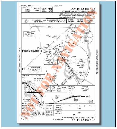
[Figure 7-9. KSTP Copter ILS Rwy 32 ]
Pilots flying Copter standard instrument approach procedures (SIAPs), other than GPS, may use the published minima with no reductions in visibility allowed. The maximum airspeed is 90 KIAS on any segment of the approach or missed approach. Figure 7-9, illustrates a helicopter only ILS runway 32 approach at St. Paul, Minnesota.
Copter ILS approaches to Category (CAT) I facilities with DAs no lower than a 200-foot HAT provide an advantage over a conventional ILS of shorter final segments, and lower minimums (based on the 20:1 missed approach surface). There are also Copter approaches with minimums as low as 100-foot HAT and 1/4 SM visibility. Approaches with a HAT below 200 foot are annotated with the note: “SPECIAL AIRCREW & AIRCRAFT CERTIFICATION REQUIRED” since the FAA must approve the helicopter and its avionics, and the flight crew must have the required experience, training, and checking.
[Figure 7-10. Part 97 Excerpt.]
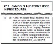
The ground facilities (approach lighting, signal in space, hold lines, maintenance, etc.) and air traffic infrastructure for CAT II ILS approaches are required to support these procedures. The helicopter must be equipped with an autopilot, flight director or head up guidance system, alternate static source (or heated static source), and radio altimeter. The pilot must have at least a private pilot helicopter certificate, an instrument helicopter rating, and a type rating if the helicopter requires a type rating. Pilot experience requires the following flight times: 250 PIC, 100 helicopter PIC, 50 night PIC, 75 hours of actual or simulated instrument flight time, including at least 25 hours of actual or simulated instrument flight time in a helicopter or a helicopter flight simulator, and the appropriate recent experience, training and check. For “Copter” CAT II ILS operations below 200 feet HAT, approach deviations are limited to 1/4 scale of the localizer or glide slope needle. Deviations beyond that require an immediate missed approach unless the pilot has at least one of the visual references in sight and otherwise meets the requirements of 14 CFR Part 91.175(c). The reward for this effort is the ability to fly “Copter” ILS approaches with minima that are sometimes below the airplane CAT II minima.
[Figure 7-11 This COPTER ILS RWY 1 approach chart for Washington/Ronald Reagan National shows the DA for helicopters is 115
feet. The Category II DA for airplanes is 165 feet ]
The procedure to apply for this certification is available from your local Flight Standards District Office.
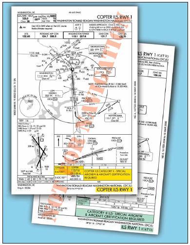
COPTER GPS APPROACHES TO AN AIRPORT OR HELIPORT
[Figure 7-12. Indianapolis Heliport Copter GPS 291°.]
Pilots flying Copter GPS or WAAS SIAPs must limit the speed to 90 KIAS on the initial and intermediate segment of the approach, and to no more than 70 KIAS on the final and missed approach segments. If annotated, holding may also be limited to 90 KIAS to contain the helicopter within the small airspace provided for helicopter holding patterns. During testing for helicopter holding, the optimum airspeed and leg length combination was determined to be 90 KIAS with a 3 NM outbound leg length. Consideration was given to the wind drift on the dead reckoning entry leg at slower speeds, the turn radius at faster airspeeds, and the ability of the helicopter in strong wind conditions to intercept the inbound course prior to the holding fix. The published minimums are to be used with no visibility reductions allowed. Figure 7-12 is an example of a Copter GPS PinS approach that allows the helicopter to fly VFR from the MAP to the heliport.
The final and missed approach protected airspace providing obstacle and terrain avoidance is based on 70 KIAS, with a maximum 10-knot tailwind component. It is absolutely essential that pilots adhere to the 70 KIAS limitation in procedures that include an immediate climbing and turning missed approach. Exceeding the airspeed restriction increases the turning radius significantly, and can cause the helicopter to leave the missed approach protected airspace. This may result in controlled flight into terrain (CFIT) or obstacles.
If a helicopter has a VMINI greater than 70 knots, then it will not be capable of conducting this type of approach. Similarly, if the autopilot in “go-around” mode climbs at a VYI greater than 70 knots, then that mode cannot be used. It is the responsibility of the pilot to determine compliance with missed approach climb gradient requirements when operating at speeds other than VY or VYI. Missed approaches that specify an “IMMEDIATE CLIMBING TURN” have no provision for a straight ahead climbing segment before turning. A straight segment will result in exceeding the protected airspace limits.
Protected obstacle clearance areas and surfaces for the missed approach are established on the assumption that the missed approach is initiated at the DA point and for nonprecision approaches no lower than the MDA at the MAP (normally at the threshold of the approach end of the runway). The pilot must begin the missed approach at those points! Flying beyond either point before beginning the missed approach will result in flying below the protected OCS and can result in a collision with an obstacle.
The missed approach segment TERPS criteria for all Copter approaches take advantage of the helicopter’s climb capabilities at slow airspeeds, resulting in high climb gradients.
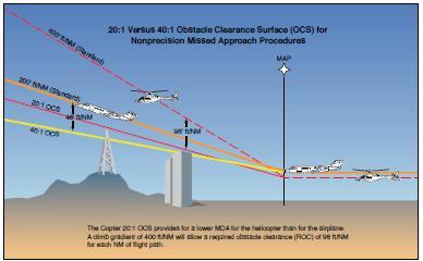
[Figure 7-13. Obstacle Clearance Surface]
The OCS used to evaluate the missed approach is a 20:1 inclined plane. This surface is twice as steep for the helicopter as the OCS used to evaluate the airplane missed approach segment. The helicopter climb gradient is therefore required to be double that of the airplane’s required missed approach climb gradient.
A minimum climb gradient of at least 400 feet per NM is required unless a higher gradient is published on the approach chart; e.g., a helicopter with a ground speed of 70 knots is required to climb at a rate of 467 feet per minute (FPM)2. The advantage of using the 20:1 OCS for the helicopter missed approach segment instead of the 40:1 OCS used for the airplane is that obstacles that penetrate the 40:1 missed approach segment may not have to be considered. The result is the DA/MDA may be lower for helicopters than for other aircraft. The minimum required climb gradient of 400 feet per NM for the helicopter in a missed approach will provide 96 feet of required obstacle clearance (ROC) for each NM of flight path.
2467 FPM = 70 KIAS x 400 feet per NM/60 seconds
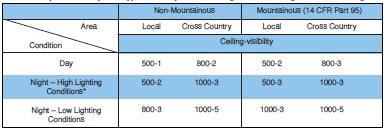
[Figure 7-14.Weather Minimums and Lighting Conditions for HEMS Operators]
HELICOPTER APPROACHES TO VFR HELIPORTS
Helicopter approaches to VFR heliports are normally developed either as public procedures to a point-inspace (PinS) that may serve more than one heliport or as a Special procedure to a specific VFR heliport that requires pilot training due to its unique characteristics. These approaches can be developed using VOR or ADF, but RNAV using GPS is the most common system used today. In the future, RNAV using the wide area augmentation system (WAAS) offers the most advantages because it can provide lower approach minimums, narrower route widths to support a network of approaches, and may allow the heliport to be used as an alternate. A majority of the special procedures to a specific VFR heliport are developed in support of helicopter emergency medical services (HEMS) operators and have a “Proceed Visually” segment between the MAP and the heliport. Public procedures are developed as a PinS approach with a “Proceed VFR” segment between the MAP and the landing area. These PinS “Proceed VFR” procedures specify a course and distance from the MAP to the available heliports in the area.
APPROACH TO A POINT-IN-SPACE
 250.JPG)
[Figure 7-15. KLGA Copter RNAV (GPS) 250]
The note associated with these procedures is: “PROCEED VFR FROM (NAMED MAP) OR CONDUCT THE SPECIFIED MISSED APPROACH.” They may be developed as a special or public procedure where the MAP is located more than 2 SM from the landing site, the turn from the final approach to the visual segment is greater than 30 degrees, or the VFR segment from the MAP to the landing site has obstructions that require pilot actions to avoid them. Figure 7-15 is an example of a public PinS approach that allows the pilot to fly to one of four heliports after reaching the MAP.
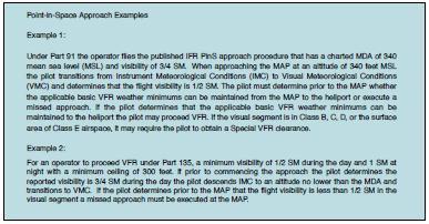 [Figure 7-16. Point-in-Space Approach Examples]]
For Part 135 operations, pilots may not begin the instrument approach unless the latest weather report indicates that the weather conditions are at or above the authorized IFR or VFR minimums as required by the class of airspace, operating rule and/or OpsSpecs, whichever is higher. Visual contact with the landing site is not required; however, prior to the MAP, for either Part 91 or 135 operators, the pilot must determine if the flight visibility meets the basic VFR minimums required by the class of airspace, operating rule and/or OpsSpecs (whichever is higher). The visibility is limited to no lower than that published in the procedure until canceling IFR. If VFR minimums do not exist, then the published missed approach procedure must be executed. The pilot must contact air traffic control upon reaching the MAP, or as soon as practical after that, and advise whether executing the missed approach or canceling IFR and proceeding VFR. Figure 7-16 provides examples of the procedures used during a PinS approach for Part 91 and Part 135 operations.
To proceed VFR in uncontrolled airspace, Part 135 operators are required to have at least 1/2 SM visibility and a 300-foot ceiling. Part 135 HEMS operators must have at least 1 SM day or 2 SM night visibility and a 500-foot ceiling provided the heliport is located within 3 NM of the MAP. These minimums apply regardless of whether the approach is located on the plains of Oklahoma or in the Colorado mountains. However, for heliports located farther than 3 NM from the heliport, Part 135 HEMS operators are held to an even higher standard and the minimums and lighting conditions contained in Figure 7-14 apply to the entire route. Mountainous terrain at night with low light conditions requires a ceiling of 1,000 feet and either 3 SM or 5 SM visibility depending on whether it has been determined as part of the operator’s local flying area.
In Class B, C, D, and E surface area airspace, a SVFR clearance may be obtained if SVFR minimums exist. On your flight plan, give ATC a heads up about your intentions by entering the following in the remarks section: “Request SVFR clearance after the MAP.” APPROACH TO A SPECIFIC VFR HELIPORT The note associated with these procedures is: “
PROCEED VISUALLY FROM (NAMED MAP) OR CONDUCT THE SPECIFIED MISSED APPROACH
.” Due to their unique characteristics, these approaches require training. They are developed to hospitals, oilrigs, private heliports, etc. As Specials, they require Flight Standards approval by a Letter of Authorization (LOA) for Part 91 operators or by OpsSpecs for Part 135 operators. The heliport associated with these procedures must be located within 2 SM of the MAP, the visual segment between the MAP and the heliport evaluated for obstacle hazards, and the heliport must meet the appropriate VFR heliport recommendations of Advisory Circular 150/5390-2, Heliport Design.
The visibility minimum is based on the distance from the MAP to the heliport, among other factors, e.g., height above the heliport elevation when at the MAP MDA. The pilot is required to acquire and maintain visual contact with the heliport final approach and takeoff (FATO) area at or prior to the MAP. Obstacle or terrain avoidance from the MAP to the heliport is the responsibility of the pilot. If the required weather minimums do not exist, then the published missed approach procedure must be executed at the MAP because IFR obstruction clearance areas are not applied to the visual segment of the approach and a missed approach segment protection is not provided between the MAP and the heliport. As soon as practicable after reaching the MAP, the pilot advises ATC whether cancelling IFR and proceeding visually, or executing the missed approach.
INADVERTENT IMC
Whether it is a corporate or HEMS operation, helicopter pilots sometimes operate in challenging weather conditions. An encounter with weather that does not permit continued flight under VFR might occur when conditions do not allow for the visual determination of a usable horizon (e.g., fog, snow showers, or night operations over unlit surfaces such as water). Flight in conditions of limited visual contrast should be avoided since this can result in a loss of horizontal or surface reference, and obstacles such as wires become perceptually invisible. To prevent spatial disorientation, loss of control (LOC) or CFIT, pilots should slow the helicopter to a speed that will provide a controlled deceleration in the distance equal to the forward visibility. The pilot should look for terrain that provides sufficient contrast to either continue the flight or to make a precautionary landing. If spatial disorientation occurs, and a climb into instrument meteorological conditions is not feasible due to fuel state, icing conditions, equipment, etc., make every effort to land the helicopter with a slight forward descent to prevent any sideward or rearward motion.
All helicopter pilots should receive training on avoidance and recovery from inadvertent IMC with emphasis on avoidance. An unplanned transition from VFR to IFR flight is an emergency that involves a different set of pilot actions. It requires the use of different navigation and operational procedures, interaction with ATC, and crewmember resource management (CRM). Consideration should be given to the local flying area’s terrain, airspace, air traffic facilities, weather (including seasonal affects such as icing and thunderstorms), and available airfield/heliport approaches.
Training should emphasize the identification of circumstances conducive to inadvertent IMC and a strategy to abandon continued VFR flight in deteriorating conditions.3 This strategy should include a minimum altitude/airspeed combination that provides for an off-airport/heliport landing, diverting to better conditions, or initiating an emergency transition to IFR. Pilots should be able to readily identify the minimum initial altitude and course in order to avoid CFIT. Current IFR en route and approach charts for the route of flight are essential. A GPS navigation receiver with a moving map provides exceptional situational awareness for terrain and obstacle avoidance.
Training for an emergency transition to IFR should include full and partial panel instrument flight, unusual attitude recovery, ATC communications, and instrument approaches. If an ILS is available and the helicopter is equipped, an ILS approach should be made. Otherwise, if the helicopter is equipped with an IFR approach-capable GPS receiver with a current database, a GPS approach should be made. If neither an ILS nor GPS procedure is available use another instrument approach.
Upon entering inadvertent IMC, priority must be given to control of the helicopter. Keep it simple and take one action at a time.
• Control. First use the wings on the attitude indicator to level the helicopter. Maintain heading and increase to climb power. Establish climb airspeed at the best angle of climb but no slower than VMINI.
• Climb. Climb straight ahead until your crosscheck is established. Then make a turn only to avoid terrain or objects. If an altitude has not been previously established with ATC to climb to for inadvertent IMC, then you should climb to an altitude that is at least 1,000 feet above the highest known object, and that allows for contacting ATC.
• Communicate. Attempt to contact ATC as soon as the helicopter is stabilized in the climb and headed away from danger. If the appropriate frequency is not known you should attempt to contact ATC on either VHF 121.5 or UHF 243.0. Initial information provided to ATC should be your approximate location, that inadvertent IMC has been encountered and an emergency climb has been made, your altitude, amount of flight time remaining (fuel state), and number of persons on board. You should then request a vector to either VFR weather conditions or to the nearest suitable airport/heliport that conditions will support a successful approach. If unable to contact ATC and a transponder code has not been previously established with ATC for inadvertent IMC, change the transponder code to 7700.
3 A radio altimeter is a necessity for alerting the pilot when inadvertently going below the minimum altitude. Barometric altimeters are subject to inaccuracies that become important in helicopter IFR operations, especially in cold temperatures.
IFR HELIPORTS
Advisory Circular 150/5390-2, Heliport Design, provides recommendations for heliport design to support non-precision, approach with vertical guidance (APV), and precision approaches to a heliport. When a heliport does not meet the criteria of this AC, FAA Order 8260.42, Helicopter Global Positioning System (GPS)
Nonprecision Approach Criteria, requires that an instrument approach be published as a SPECIAL procedure with annotations that special aircrew qualifications are required to fly the procedure. Currently there are no operational civil IFR heliports in the U.S. although the U.S. military has some nonprecision and precision approach procedures to IFR heliports.
Copyright © 2008 AirplaneGroundSchools.com | All Rights Reserved
Design G. Wolfgang | W3C XHTML 1.0 | W3C CSS 2.0
Courtesy Open Web Design![]() Thanks to Florida Vacation Homes
Thanks to Florida Vacation Homes